This thread has been locked.

If you have a related question, please click the "Ask a related question" button in the top right corner. The newly created question will be automatically linked to this question.

UCC28070 intermediate tripping of gate pulses

Other Parts Discussed in Thread: UCC28070

Hi,

I am using UCC28070 in 3KW PFC application and i am facing problem like my pulses are tripping when i am testing at full load condition.Please see the below wave forms;

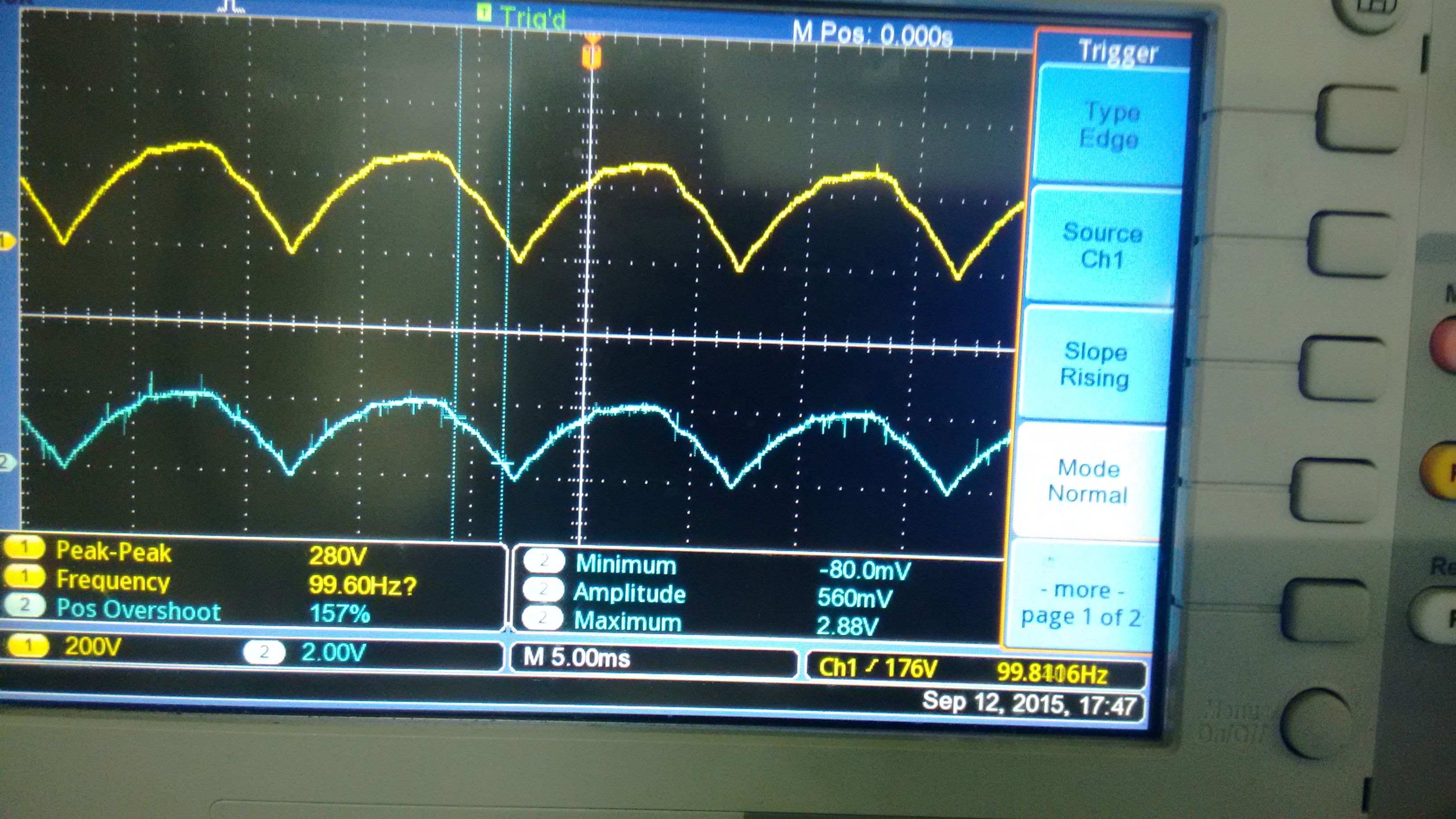
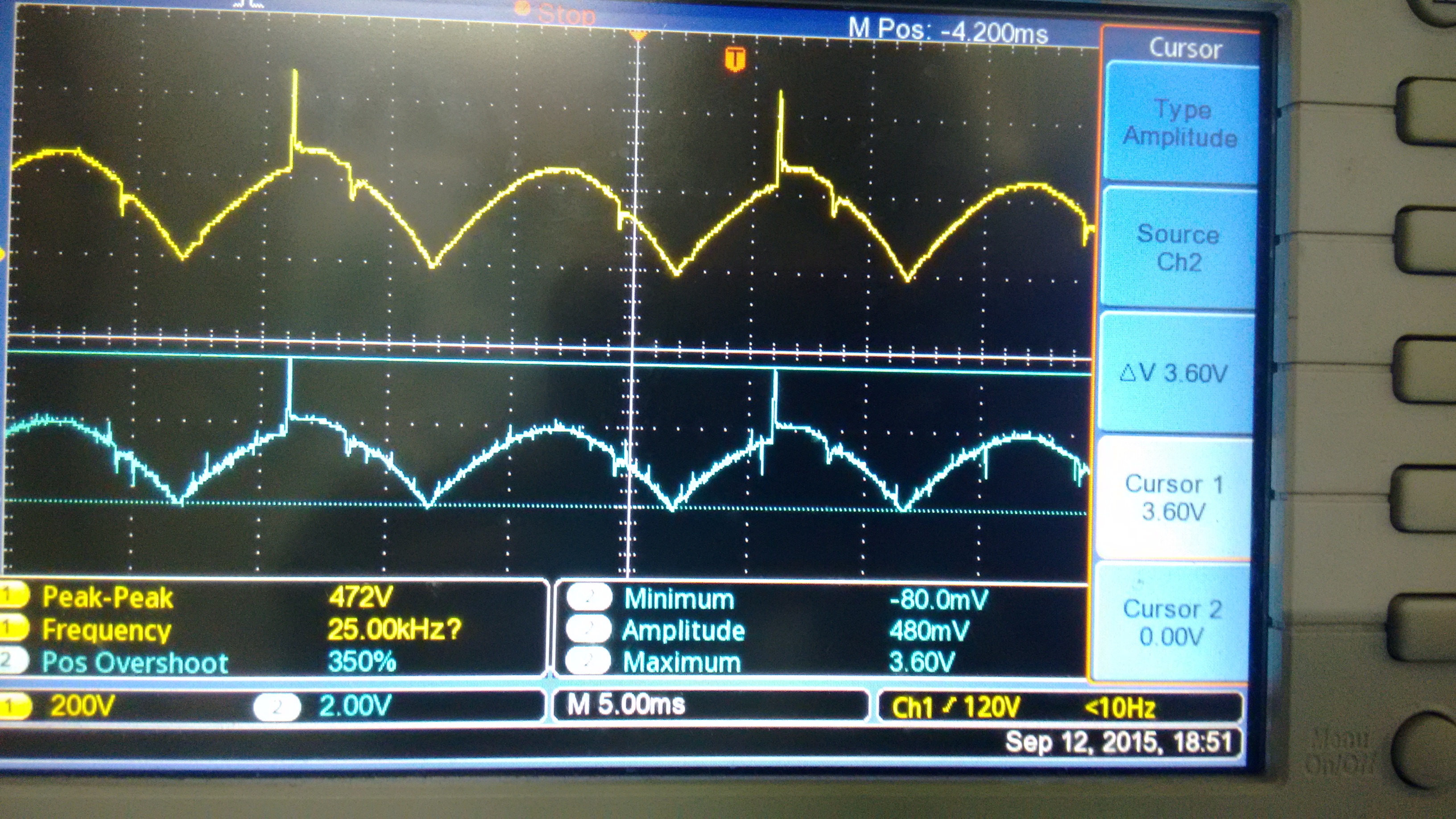
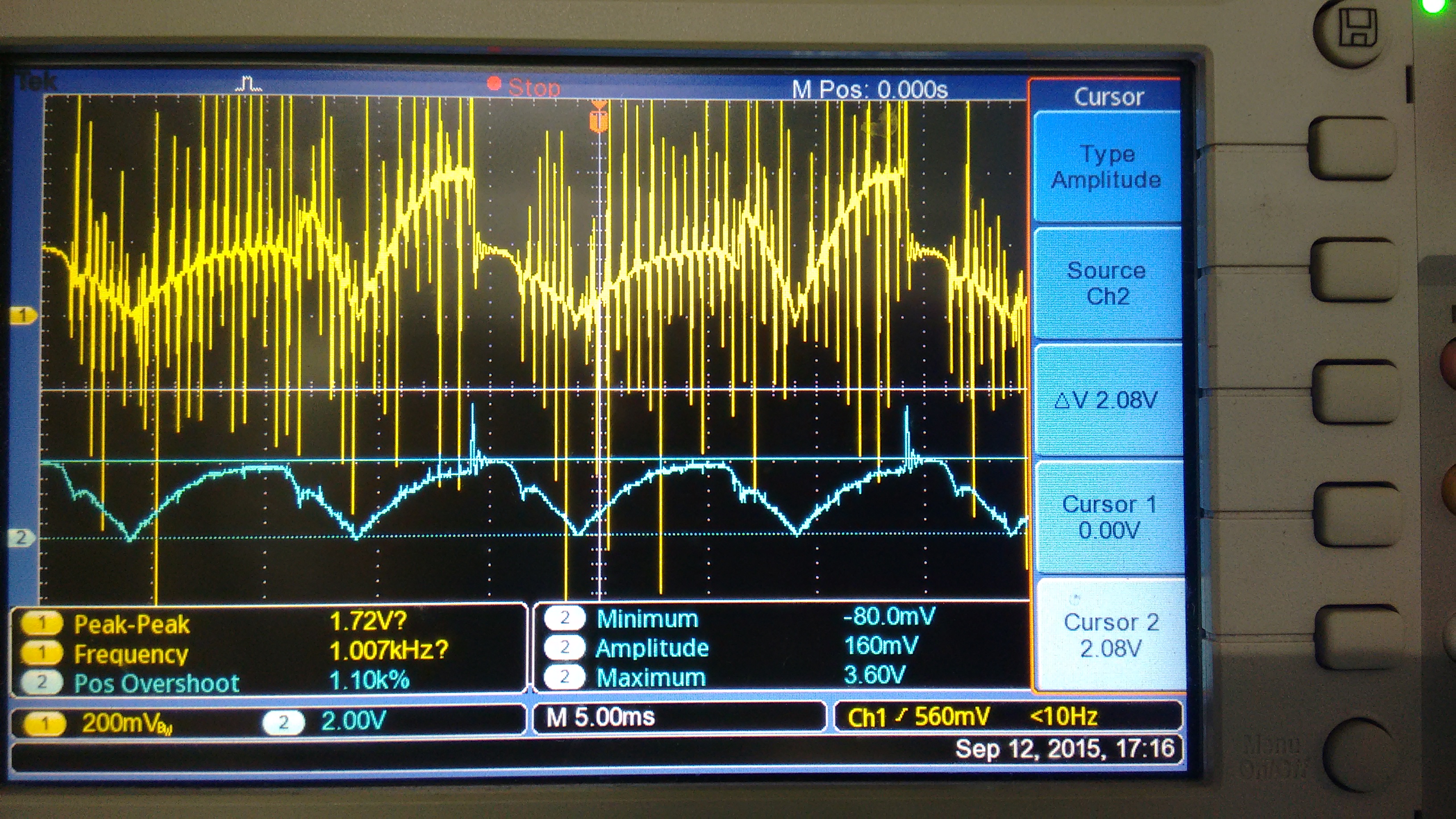
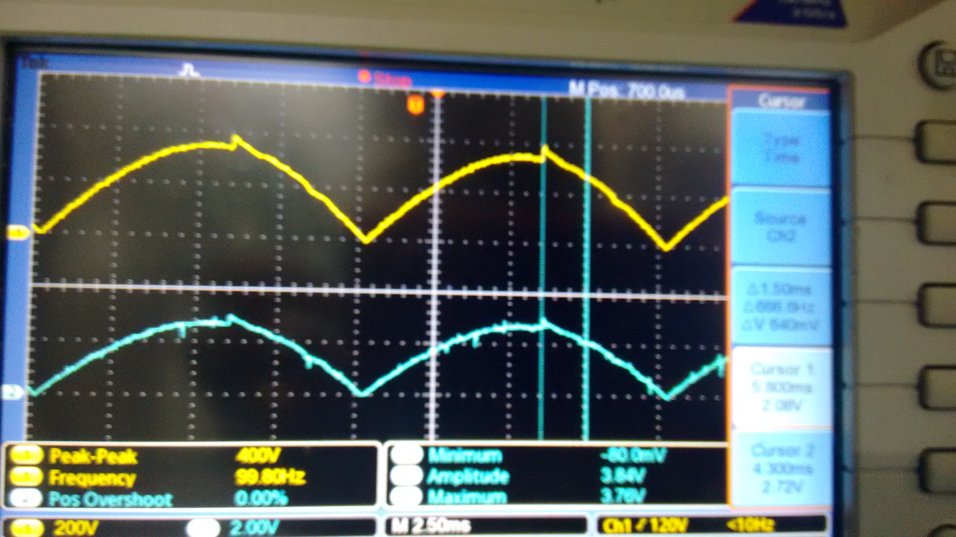
Below is the Current wave form at 220V AC: (CH1 shows current wave form and CH2 shows VAO wave form)

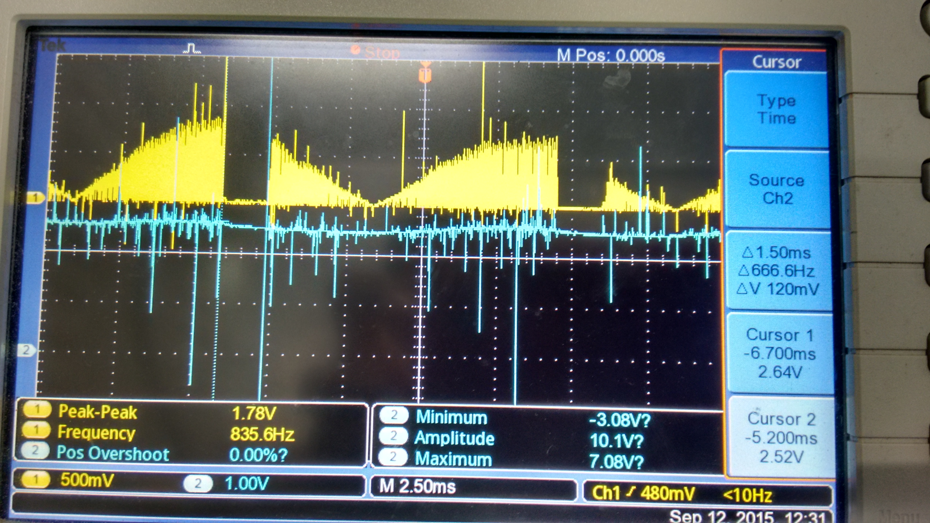
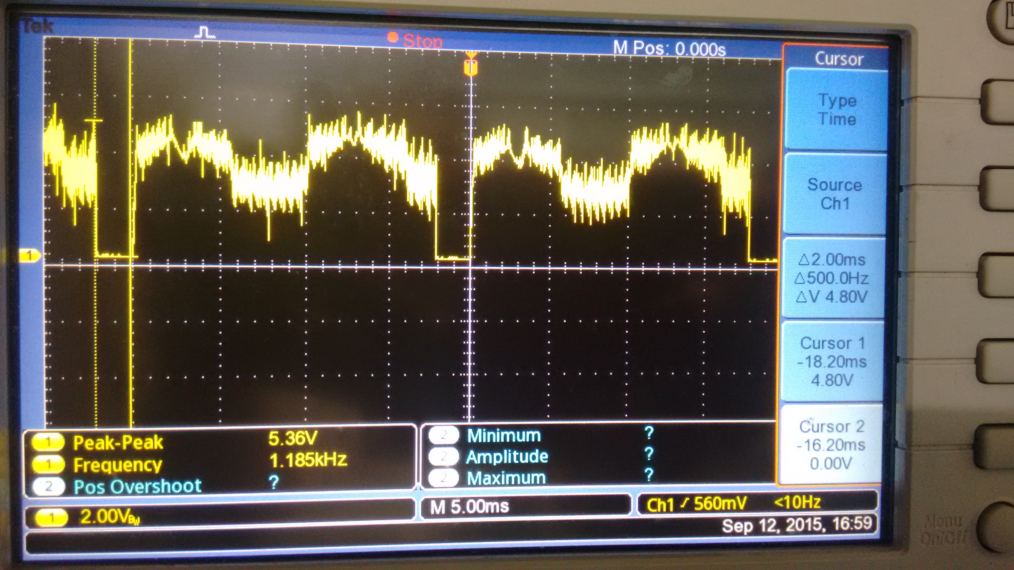
Below is the waveform at IMO pin:

My design calculations:

Minimum RMS Input Voltage VIN_MIN 85 V
Maximum RMS Input Voltage VIN_MAX 275 V
Minimum Line Frequency fLINE 47 Hz
Maximum Line Frequency 63 Hz
Maximum Output Power POUT 3000 W
Full Load Efficiency (Must be less than 0.99) η 0.90
Switching Frequency fS 6.00E+04 Hz
Output Voltage VOUT 400 V
Maximum Duty Cycle DMAX 0.90
VCC 15 V
L1_MIN, L2_MIN 400uH
L1_MAX, L2_MAX 900uH
Average Inductance Value L1_AVG, L2_AVG 650uH
Current Sense Transformer Turns Ratio NCT=NS/NP 200
Current Sense Peak Voltage VS 3.00 V
Current Sense Resistor RSA = RSB 10 ohm
Current Sense Offset VOFF 0.00 V
High Side Resistor on Peak Current Limit Divider RPK1 6.80E+03 ohm
Low Side Resistor on Peak Current Limit Divider RPK2 6.80E+03 ohm
Select Timing Resistor RRT 120Kohm
RDMX 100K
Side Resistor for VSENSE Voltage Divider RA 9.60E+05 ohm
Low Side Resistor on VSENSE voltage Divider RB 7.25E+03 ohm
CPV 220nF
RZV 51K
CZV 2.2uF
RSYN 130K
RIMO 15K
RZC1=RZC2 51K
CZC1=CZC2 470pf
CPC1=CPC2 100pf

I tried with different compensation values but not able to solve the problem. Can any one help me out to fix the problem. 

  • hi,

    Recently i found that above problem is starting when i am decreasing my input voltage from 230v (using variac). When i am decreasing the voltage below 220v problem was starting and some times it is recovering when i increased the voltage to 240 or 250v. Without variac I tested my unit at full load and it's working fine ( At the time of testing my input voltage is 235v).

    I found that when the problem was started there was a spike in input AC voltage and the same spike was appearing on the Vac pin also.

    Below are the AC wave forms :

    Before problem starting : (Ch1: Mains AC and CH2: Signal at VAC Pin of IC)


    After problem starting : (Ch1: Mains AC and CH2: Signal at VAC Pin of IC)

    From above waveform we can see the sudden rise in input voltage. I think it may be because of sudden change in current through inductive vatiac. But i am not getting why the gate pulses are suddenly tripping. My peak current setting was far away from the current sensing signals. And one more thing whey it is coming exactly at same location of AC wave form.

    After problem starting : (Ch1: Wave form at IMO pin and Ch2: Vac pin)

    After problem starting : (Ch1: Wave form at CAOA pin)

    After problem occurred i increased my input voltage and it's starts recovering but not fully. See the below wave form at increased voltage condition. 

    And i also found that the problem is not coming when i loaded at 180v and increasing upto 230v.

    Help me if you found any solution or if you got any idea why the problem is starting.

  • I think you have found the source of the problem with the waveform on the VINAC pin.
    The UCC28070 has a quantized linear multiplier and this means it monitors the peak of the VINAC waveform and uses this block to set the gain of the voltage error block.
    Your circuit has a spike that causes the input signal to jump from about 2V to 4V for a time duration of about 200uSecs.
    This will cause the multiplier to mistakenly set the KVFF at the highest level. The reference signal into the current loop is now too low all of a sudden.
    The result is that the pfc circuit will not be able to maintain the output voltage setting.
    Its hard to tell from your first waveforms but it looks like your loop is going unstable and trying to recover.

    Can you please:

    (1) Recalculate the values for the VINAC resistors.
    For a 220Vac input, you need about 1.65V peak on VINAC. (You have about 2.4V)
    See Table 1 in the datasheet.

    (2)  Place a small filter capacitor on VINAC

    (3) Identify the source of the spike in your circuit and try to eliminate it.

    Regards,

    John Griffin

  • Hi Mr.John,
    Thanks for your reply. Please see the below comments;
    1. Presently i am using same resistor divider configuration for the Vsense and Vac inputs.
    Present Values: Hi side resistor = 960K; Low side resistor = 7.25k (for the both Vsense and Vac)
    Required output voltage=400v.
    At 220vAC input if you want to maintain 1.65v peak on the VinAC pin then we may have to use different resistor dividers for Vsense and VinAC.
    I have gone through the table 1 in the datasheet and it was mentioned that 1.65v is for 220 Vinpeak voltage (it's 155v rms). Please correct me if i am wrong.

    I have gone through all your example circuits and in all of them they used near about 3M for high side and 25k for low side. I will check my board with the same configuration and come back to you.

    2. Presently i am using 220pf filter capacitor on VINAC pin and also tested with 1nf but there was no much improvement.

    3. As i mentioned earlier the spike is because of sudden current changes in the inductive variac (to change my input voltages I am using variac) . But this sudden change in current was happening because of misbehavior in the PFC circuit (gate pulses are tripping suddenly). I think after gate pulses tripping only this spike is appearing on the input ac signal.

    We need to find out why this sudden tripping in gate signals are happening; it's because of problem in voltage loop, current loop or any other factors.

    I will post you if you need any further wave forms. Please share me your mail id so that i can share you the circuit and excel design tool sheet.

    Thanks and regards,
    Ashok
  • Hi Ashok,
    You can contact me at johngriffin@ti.com

    Regards,
    John
  • Dear Mr.John,
    I tested my board by changing the resistor configuration ( 3.01M for high side and 23k for low side) but i haven't got any improvement.
    Regards,
    Ashok
  • I sent you the circuit and excel sheet through mail. Please check and revert back if you found any issue.
    Regards,
    Ashok