This thread has been locked.

If you have a related question, please click the "Ask a related question" button in the top right corner. The newly created question will be automatically linked to this question.

BQ76PL536 sleep consumption

Other Parts Discussed in Thread: BQ76PL536

Hi,

We are currently using two stacked BQ76PL536 to monitor 12 cells.

Activation of sleep mode is properly working.

Top BMS of the stack consumption is 15uA (which is compliant with the datasheet)

Bottom BMS consumption is 46uA. This is out of the datasheet specification. Is it usual that the host BMS requires more current in sleep mode? Otherwise are there other requirements (exept those in the datasheet) to follow? 

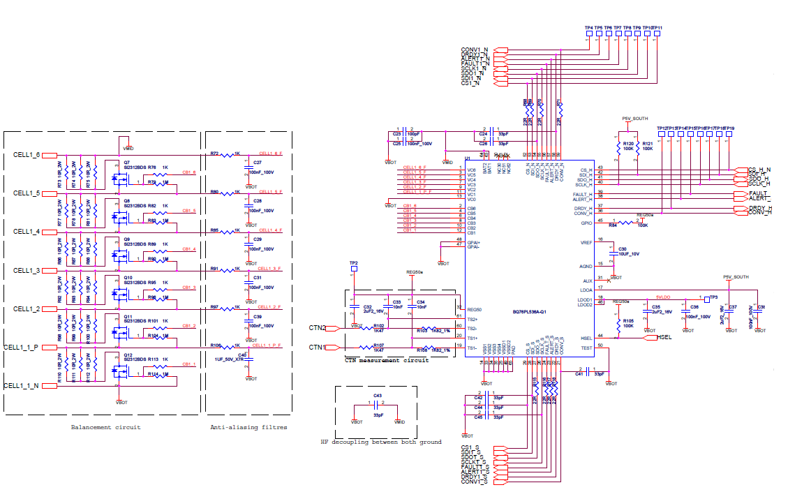
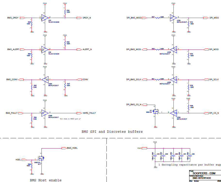
Below is the schematic of the south BMS and its buffered communication signals (P3V3 is down in sleep mode)

Buffered signals (P3V3 is down in sleep mode): 

Regards

Pierre

  • HI Pierre,

    I don't think you need a pull up to reg50 on Hsel Pin.
    I reviewed the schematic and it's little be not clear how HSEL is connect to GND(host mode).
    For upper IC, It has to connect to LDOD.

    Is BMS_DRDY connected to PL536A side or to the uC?
    DRDY is asserted all the time except when ADC is converting.
    It seems to me that BMS_DRDY is connected to PL536A side. If it is then you have the leakage path through R58

    Can you also measure reg50 on bottom IC? Should be 0V. That's how you can tell whether IC is in sleep or not.

    Check BMS_DRDY.

    If not then send me whole schematic.
  • HI Roger,

    First thanks for your answer. Below are my answers:

    I reviewed the schematic and it's little be not clear how HSEL is connect to GND(host mode). 

    [PIERRE]: HSEL is open drain and pulled low by the uC

    For upper IC, It has to connect to LDOD. 

    [PIERRE]: It is actually connected to LDOA as it is advised in the datasheet that overvoltage can occur on LDODx
    Is BMS_DRDY connected to PL536A side or to the uC? 
    DRDY is asserted all the time except when ADC is converting. 
    It seems to me that BMS_DRDY is connected to PL536A side. If it is then you have the leakage path through R58
    Can you also measure reg50 on bottom IC? Should be 0V. That's how you can tell whether IC is in sleep or not. 

    Check BMS_DRDY. 

    [PIERRE]: BMS_DRDY is connected on BMS side and DRDY_N on uC. I don't have the board anymore but by the time we were performing measurements in sleep mode, REG50 was indeed 0V. I don't remember what was BMS_DRDY voltage at this point. Maybe it can explain the leakage. What is supposed to be level of DRDY in sleep mode?

    Regards

    Pierre

  • I recommend to most of customer to float the DRDY_H pin and have uC wait ~1mS. Unless, you truly monitor the DRDY_H pin. I think DRDY_H default is high state which is min of 4.5V. I think it's asserted in sleep mode but I will double confirm with our evm. I will let you know by tomorrow if it's otherwise.. Is everything else working okay with your board?
  • Hi Roger,

    It looks like leakage come from DRDY_H. As I am not able to check that by my own, I'm looking forward your double check on your evm.

    Everything but this point is doing great. This is our last concern.

    Thanks

  • DRDY_H is asserted in sleepmode as I expected. 

    That could be your additional leakage path. You might want to check into that. 

    Check out and let me know then we will figure out.