This thread has been locked.

If you have a related question, please click the "Ask a related question" button in the top right corner. The newly created question will be automatically linked to this question.

TPS92513 Visense temperature characteristic

Other Parts Discussed in Thread: TPS92513

Hi,

My customer has question about TPS92513.
Could you tell me about questoin?

[Question]
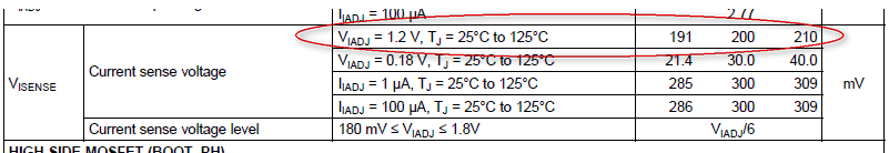
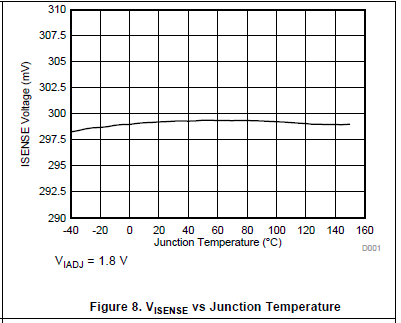
 Is there Visense temperature characreristic at Viadj=1.0V?
 How much does it vary by temperature?

Best Regards,
tateo

  • Hi Yamashiro-san,

    I will need to confirm the temperature dependence on this with the development team.

    Regards,

  • HI Yamashiro-san,

    I got some feedback from the team much faster than expected!


    In the datasheet we do show two ranges of VIADJ:

    So regardles on VIADJ, the change over temperature is about the same. The below graph shows the overall shift over temperature:

    So most of the deviation appears to be at very cold temperatures.

    I hope this helps to answer your question.

  • Thank you for your reply.

    In datasheet, Vsense is good accuracy +/-3% at Viadj=1.8V. But Vsense becomes low accuracy as Viadj is the lower.
    Is the temperature characterisitic about the same at Viadj=1V?

    Now my customer is evaluating TPS92513 at Ta=75C on his prottype board. When the device keeps operation, Iled become to up +17%.
    My customer can't solve this problem. So he want some hint.

    Best Regards,
    tateo

  • The variation due to temperature and offsets is about 9mV to 10mV as you can see in each spec. This will be the same for Viadj=1V.
    As for the +17%, I would need to have more information like input/output voltages, LED stack voltage and current, and a schematic and BOM if possible. It is likely that the cause is something else in the circuit that is not behaving at higher temps since we have tested the TPS92513 over temp successfully many times. Did you check to make sure the voltage at the IADJ pin is still what you expect as well?
  • Thank you for your reply.
    Schematic and Waveform is figure below.
    Could you help us?

    Best Regards,
    tateo

  • From that all I can tell is that it looks like the switching frequency is too high for the inductor value chosen. For proper current mode regulation you need a certain amount of inductor ripple as stated in the datasheet. This may not be the issue for sure, but it is possible since the added noise at high temperature could be more likely to confuse the error amplifier. But I don't know your Vin, Vout, and Iout conditions to be sure. Could you provide those? Did you check that IADJ is still solidly at 1V when the current rises?

    Other than that I would suspect a component (for example inductors lose inductance when hot and the rms current can rise, or it can be near saturation and the output current can rise) or layout. If you could provide a BOM that would be helpful, and if you are using a layout other than the EVM I would be happy to look that over as well. Thanks.

  • Thank you for your reply.
    I'll send more information.

    And I have one more question.
    In the EVM user's guide, Figure 5 shows the output current vs Iadj test point voltage.
    In figure, LED current is 650mA at IADJ voltage=1V. I calculate LED current at IADJ voltage=1V.
     Rsense=0.3ohm
     IADJ voltage=1V
     LED current = (1/6 * 1V) / 0.3ohm
                         = 555mA
    EVM's LED current is higher than calculate the value. Why is EVM's LED current is higher than culculate the value?

    Best Regards,
    tateo

  • Every once in a while we produce a graph with measurement error, you have caught one of them. It looks like there is some offset, I am not sure from where. But you are correct, that graph is not accurate. The linearity is fine and that is partly what it is supposed to show. But the absolute numbers are off and the current would be closer to 550mA at 1V IADJ if measured correctly.