This thread has been locked.

If you have a related question, please click the "Ask a related question" button in the top right corner. The newly created question will be automatically linked to this question.

-12 V to +5 V at 2 A, efficient switching supply?

Other Parts Discussed in Thread: TPS61175

I scanned the Simple Switcher forum, but the non-isolated DC/DC forum seems like a better fit.

I have -12 V ±5% on input and need a reasonably well-regulated +5 V output at a minimum of 1 A, preferably 2 A. I'd like to be somewhat efficient, so I'd like to avoid a linear solution. I also need to filter both directions so that my switcher does not create noise on the -12 V supply or on the +5 V output. The output will probably be easier to filter. I assume the input might need some resistance for isolation, which will understandably reduce efficiency. In that case, efficiency is not as much of a priority as low noise, so long as the efficiency is better than typical linear inverting supplies.

Any hints? I'm also hoping for low parts count, but perhaps I'm asking for too much?

p.s. I'd like to support input voltages as high as -18 V, although the -12 V 5% is most likely.

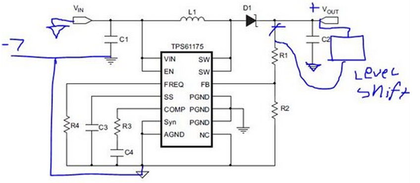
  • maybe you need a circuit as following. it should work, but i didn't validation it before. you can apply an EVM for validation. may i know why customer need negative input voltage and positive output voltage.

  • Jasper, what is the "level shift" ? I was hoping to find a low part count, so, would a Zener work as a level shift in this? Seems like it is unneeded, since the R1/R2 voltage divider could easily work between +5 V and -12 V without level shift. Or, it might be necessary to put the level shift on the other side of R2, so that the FB node does not go negative.

    Are you sure that PGND can be 12 V above AGND? I haven't looked at the TPS61175 data sheet yet. Does it have any negative to positive example circuits?

    I see that you posted this same answer to another question, but didn't change the -7 V to -12 V. Has anyone done this? Do any of the Texas Instruments TPS chips have negative to positive example circuits in their data sheets?

  • Please refer this application note i just found it "Negative Input to Positive Output made SIMPLE" (http://www.ti.com/lit/an/snva740/snva740.pdf). because the GND pin voltage is the input negative voltage, a level circuit is needed.

    all the gound pin (AGND, PGND) of the IC must be the lowest voltage, which is -12V in the application.

  • Thanks for the clarification, Jasper. SNVA740 helps.

    p.s. I think that you should correct the schematic that you're sharing, since it shows PGND connected to 0 V and AGND connected to -7 V.