This thread has been locked.

If you have a related question, please click the "Ask a related question" button in the top right corner. The newly created question will be automatically linked to this question.

How to connect a BQ24261 to a micro-controller using I2C interface ?


I am very new to the charger board and dont have the USB-GPIO interface board.

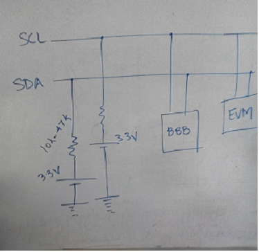
Can I connect my BQ-24261 battery charging board to by TIVA-C launchpad (or other micro-controller boards like Beaglebone Black, Aruduino, Rasp Pi) using the I2C interface ? i want to be able to programatically set the charging voltage. 

If yes, can I get some sample code and other hardware needed to accomplish the same ?

- Thanks and Regards

Chintan Pathak 

  • You can connect the charger's SDA and SCL lines directly to u-controller SDA SCL lines. The charger does not have a processor. The code will only be reads and writes of I2C registers. We are in the process of posting example code to github.com/tibms
  • A publically available driver is available here: lkml.org/.../91
  • Please humor me and keep this question open, as I might need a little more hand holding. 

    As per my understanding of the I2C (correct me if I am wrong), a read and write operation can be performed on the EVM considering it as slave and BBB as master, using function calls like i2c_read (...) and i2c_write(...). Before I begin to wire things up and write this implementation, I had a few follow-up questions: 

    1. What is the address of the I2C registers on EVM or even the base address ? I wasnt able to find anything in the user's guide. Any other official documentation regarding the EVM other than the user's guide ? 

    2.  What voltage should I use to power the I2C ? I am planning to connect the two devices as shown in the image

    Is a voltage of 3.3 V sufficient / proper for our EVM ? and pull-ups of 47k. I plan to get this voltage from the BBB. 

    3.  I tried elsewhere as well, I couldnt find the library referred to here: lkml.org/.../91 . How can I get the files bq24261_charger.c amd bq24261_charger.h latest. I found an old commit by on of the authors here:  https://github.com/ZenfoneArea/android_kernel_asus_zenfone5/blob/master/linux/modules/drivers/power/bq24261_charger.c . Also any guidance on how to use this library ?

    Ultimately, using the library, or other code, we should be able to set the charging voltage and current to be derived from the EVM using the I2C connection from BBB. 

  • Reading the datasheet was quite enlightening and I am marching further on my way.

    To summarise: I found out how to set the Battery Regulation voltage and charge current, thanks to register descriptions on page number 33-35, which use the formula
                                             
                                           VBATREG = 3.5 V + VBREGCODE × 20 mV 
                                    and     ICHARGE = 500 mA + ICHRGCODE × 100 mA
    Also, I found the address of the EVM for referring in my BBB I2C code as : 0x6B (1101011 in binary) .
    Now, I am left with two, seemingly non-trivial questions, 
    1.  How to do I write to the registers like the Status/Control Register with a memory location of 00, Control/Battery Voltage Register with a memory location of 02, etc. I learnt direct register manipulation (DRM) but then experts suggested that using API function calls is a safer method to use than DRM (I dont think such API functions are available for BQ-24261, there was a mention of a public library here https://lkml.org/lkml/headers/2015/9/6/91 but I couldnt locate the actual header file) , so I am not as thorough with the process. A two line snippet would really help in clarifying the concepts. 
    2.  Choice of functional mode:Section 9.4 of datasheet, lists details about 19 possible functional modes for operating the EVM. Which of these is the suggested one ? I understand that this might be application specific, but any pointers on this selection, or this is done implicitly by setting the appropriate registers through the above step. 
    - Thanks 
    Chintan Pathak 
  • Regarding 1, standard I2C read and write commands, as explained in datasheet section 9.5, are used to read from/write to the charger's I2C registers. There are start and stop bits and the ACK bits on receipt.

    Regarding 2, the datasheet overuses the term "modes". The charger only operates in two "modes": charge or OTG boost. In charge mode, the charger runs in constant current "mode" until the battery voltage rises near VBATREG and then switches to constant voltage "mode". If I2C communication is available, the IC runs in host "mode" with certain default settings, otherwise it is in standalone "mode" with certain default settings.
  • So, I got to a code, that works, github.com/.../charger.c 
    It updates the voltage delivered by the charger every few seconds, similarly other parameters like the charging current can be tweaked. 
    Thanks a lot to all the folks, ;) 
  • Hi,

    I am so sorry to disturb you. Because I also want to use the I2c, but the link you provide is invalid now. May I kindly ask you whether you can share the code to me? Thank you very much.