This thread has been locked.

If you have a related question, please click the "Ask a related question" button in the top right corner. The newly created question will be automatically linked to this question.

TPS65910A3 VRTC 0.880 instead of 1.80v

Other Parts Discussed in Thread: AM3352

Hi All,

I am trying to power up my AM3352 custom board with an TPS65910A3.  One some boards the VRTC comes up with the VCC just fine to 1.8v... on others it powers up to 0.880v and the board does not boot.  Any ideas why the VRTC regulator would only supply 0.880v?

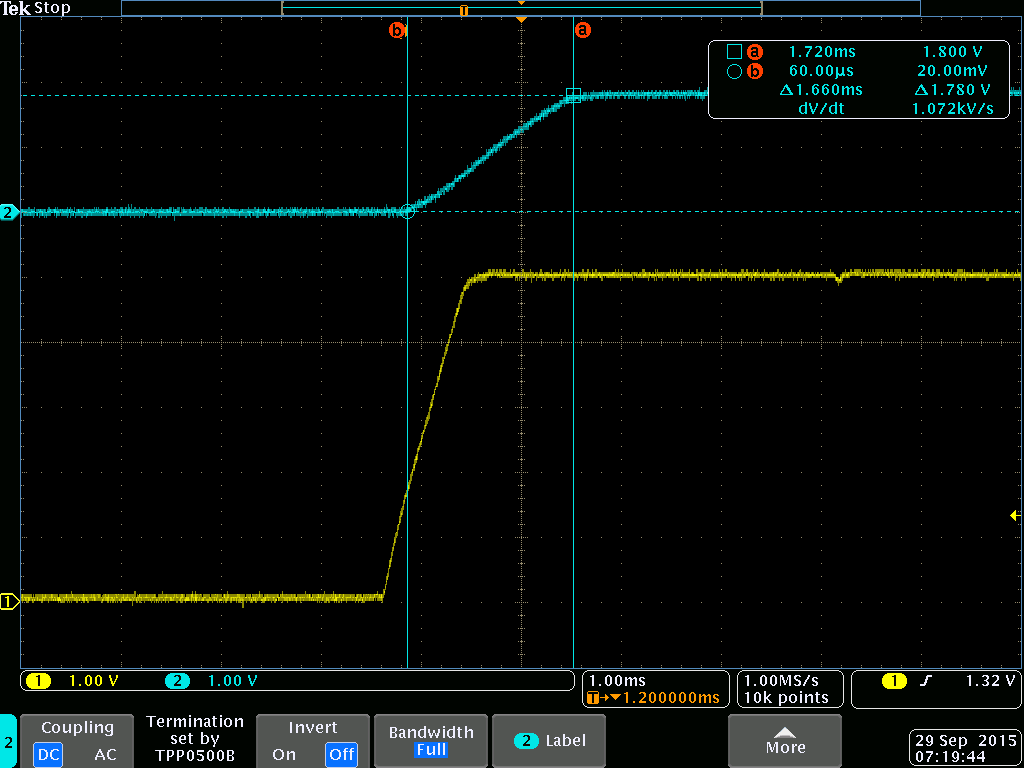
Here is a good board.  Blue is VRTC, Yellow is VBAT (in my case a 5v power supply).

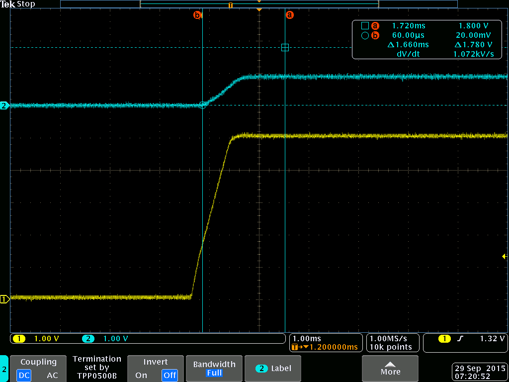
And here is a bad board.  Same colors scheme:

  • Here is the PMIC schematic page:page5.pdf

  • For the TPS65910A3, VRTC has a current limit of ~100µA in OFF mode. OFF is the first state once power is detected, so this can cause issues on startup. Are there external connections to VRTC other than BOOT and GPIO_CKSYNC? If so, removing these loads should help address the issue. Another option is to switch to the TPS65910A31, which has a higher current limit of 20mA in OFF mode. 

  • Thank you. That was it. I had the AM3352's RTC hooked up to the VRTC LDO. I removed the AM3352 and one of the boards that would not boot now boots all the time. I will sample some A31's and try them.

    BTW Is it possible to reprogram the TPS65910A3's eeprom in the field so that it acts like a A31?
  • I'm glad that worked. Unfortunately this device was not designed for customer EEPROM programmability, so there is not a method for changing EEPROM in the field.
  • Shoot. Thank you!!!
  • Richard Solarski said:
    TPS65910A31, which has a higher current limit of 20mA in OFF mode. 

    I replaced on of my A3 chips with an A31 chip.  I am having the same issue.  :-( 

    I installed a small resistor to measure the current at power up, and am only pulling 2ma, so I do not understand why the A31 can not bring up the 1.8v VRTC bus.  When I use an external power supply to provide VRTC, the chip sequences just fine.  Any ideas of where to look now?

    Chuck

  • Hi Chuck,

    Is RTC_PORZ high before VRTC is operational?

  • page2-mod.pdf

    Richard Solarski said:
    Is RTC_PORZ high before VRTC is operational?

    No, it is low before VRTC is operational.  I went and looked at the reset circuit, copied from the EVM (my version is attached) and found that the cap, C40, was too small.  I grabbed a 10uF (too big, but conveniently located on my bench) and installed it to better match the original circuit.  The board still does not come up, but the reset lags the VRTC by 7500uS.

    Chuck

  • Any more insight?

  • Hi Chuck,

    I just noticed your schematic had VCC7 tied to VBACKUP instead of +5V , is this still the case? In backup mode all VRTC LDOs have the backup current limit, the programmable bit only applies to the OFF mode current limit. The PMIC will shift into backup mode if VCC7 is less than about 2.6V and 2mA would be too much current consumption for this mode.
  • I went through all of the pins on the PMIC and created this table... It shows VCC7 at 5v.  Vcc7 is connected to a net with an unfortunate name: Vbackup, which is not pin 27 on the PMIC!

    Am3352 and TPS65910A31
    Pin Name Voltage (nearest 0.05v)
    1 pwrhold 5.0
    2 vmmc 0
    3 vcc3 5.0
    4 vax33 0
    5 vdig2 0
    6 vcc6 5.0
    7 vdig1 0
    8 sda 0
    9 scl 0
    10 sdasr/en2 0
    11 aclsr/en1 0
    12 vddio 0
    13 vccio 5.0
    14 swio 0
    15 gndio 0
    16 vfbio 0
    17 refgnd 0
    18 vref 0
    19 Boot 1 0.7
    20 osc32kin 0
    21 osc32kout 0.2
    22 vdac 0
    23 vcc5 5.0
    24 vpll 0.4
    25 testv 0.1
    26 Boot 0 0
    27 vbackup 0.05
    28 vcc7 5
    29 vrrtc 0.7
    30 vfb3 0.1
    31 sw3 0
    32 vfb1 0
    33 pwron 5
    34 gnd1 0
    35 sw1 0
    36 vcc1 5.0
    37 sleep 0
    38 clk32kout 0
    39 gpio/cksyn 0.7
    40 nrespwron 0
    41 vcc2 5.0
    42 sw2 0
    43 gnd2 0
    44 vfb2 0
    45 int1 0
    46 vaux1 0
    47 vcc4 5.0
    48 vaux2 0
  • Thank you for the clarification and the measurement table. VPLL looks like the only other regulator with odd values that might be supplied from a load. Everything else looks normal, VRTC is behaving like an A3, not an A31, which is concerning. Does the device ever get up to 1.8V? Are you still having trouble on just a few boards or are failure rates consistent across other boards?
  • Richard Solarski said:
    Does the device ever get up to 1.8V? Are you still having trouble on just a few boards or are failure rates consistent across other boards?

    I only modified one board with a A31, I did it by hand... so not that easy to replicate.  It will get to 1.8v if I remove all of the load on the VRTC.

    Here is a photo of the chip:

  • Hi Chuck,

    If the power-pad is not soldered it could cause regulation issues. Were you able to get heat to the pad? If you don't have a hot air station you might be able to get to the pad with a soldering iron using the vias below the pad.