This thread has been locked.

If you have a related question, please click the "Ask a related question" button in the top right corner. The newly created question will be automatically linked to this question.

LED pop-on using LM3445

Other Parts Discussed in Thread: LM3445

I am using the LM3445 to a single 100 Watt LED COB that uses 2.5 amps at 37 volts.

As with most dimmable LED's there is a pop-on tendency that requires the dim level to come up to a higher level to bring the LED on but this is above the lowest dim level that is observed when dimming from high to low.

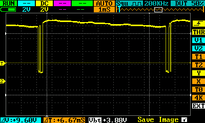
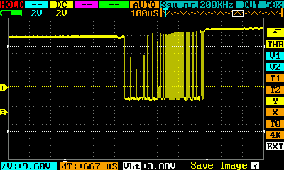
Also perhaps related is when bringing up the level from completely off the LED pops to a high level and then settles back to a lower level

My circuit essentially follows tat given in the application note.

.....www.ti.com/.../lm3445.pdf......

Has anyone experienced this phenomenon?

Is there some way to ramp up the current delivered to the LED or other means to control this overshoot?

Adding capacitance to the FLTR2 pin did not much help and had undesirable effects.

Perhaps a more developed compensators are needed but access to the feed back loops are limited.

Thanks

  • Hello,

    The LM3445 is a hysteretic controller, it will not overshoot unless it is told to overshoot by what it decodes on the angle sense pin.  Some controllers with compensation can have overshoot especially if the bandwidth is low for PFC.  If the light on power up is initally brighter the LM3445 is being told to do that via angle sense/filter1/filter2.

    There are quite a few newer dimmers that have been created for LED bulbs that have a pop-on adjustment where it sends a larger duty cycle when first powered on.  This was created because many LED bulbs come up very slow when powered on at a low dim level.  This is due to charging the LED energy storage capacitor (in low light ripple designs).

    One thing I can think of that would cause this is (if it's not one of those dimmers that provides a wide duty cycle for turn-on) if, during power on, the bleeder cannot hold the line down and it decodes a full rectified AC waveform, or something isn't connected correct and angle sense is getting a wide duty cycle at turn-on.  This would be decoded as full light output charging filter one and then filter two until there was enough load to correct the line detection which could cause a flash.  It's also possible if there is a lot of EMI capacitance from rectified AC to system common.

    I have a few questions related to this:

    Is this design a valley fill on the front end?

    Is the bleeder pin connected before the isolation diode to the valley fill?

    Does the dimmer being used have the pop-on feature?  I've seen the adjustable ones with the white and black adjusting wheels hidden behind the dimmer cover.  You can check this if you have an oscilloscope watching the input current or rectifed AC.  Note this is a non-isolated design so it is important to know how to measure waveforms and prevent getting injured/damaging test equipement.

    What test equipment do you have available?

    How is Coff connected?  If it's reflected back to system common with a PNP it should be okay but there are different ways to use Coff.

    There are ways to add a soft-start circuit.  Making Filter 2 capacitor large is one but you may run into issues when adjusting the dimmer.

    Thanks,

  • Irwin,

    Thanks for the reply.

    There is a two stage valley fill circuit and the bleeder pin is before the isolation diode.

    The dimmer is a standard one used in theatrical lighting and may have pop on feature which I will verify......

    I have full set of test equipment including digital scopes and spectrum analyzers.

    Coff is simply connected from the low voltage supply to the controller chip through a resistor and capacitor.

  • Hello Wade,

    It might be easiest to look at the input current and/or the rectified AC, bleeder pin and/or angle sense pin during turn on. It's a non-isolated design so you have to be careful how you connect the oscilloscope (probe ground connection can cause 1/2 cycle short through rectifier bridge). If the bleeder/angle sense duty cycle is high at initial turn on then drops that could cause a flash.

    Another thing to try would be to run an incandescent bulb (or power resistor) in parallel with the the LED driver to see if the dimmer is getting reset during the power up sequence. It should be fairly easy to figure out what is going on, fixing it may be a different story.

    As for the dimmer, is this a triac phase cut (forward phase) or a reverse phase. There can be issues with reverse phase because of the valley fill and dimmer loading.

    Thanks,
  • Irwin,

    Adding an incandescent bulb does not eliminate the pop-on issue.

    I captured some scope traces of the gate waveform. 

    It shows that before the pop occurs the gate is mostly high and after it settles to the expected short on time for very low dim levels. 

    The gate is on most of the time before the pop on and the next two pictures zoom in on the  portion where it is switching.

    zoom in on the points where the gate signal is low which happens when the AC main zero cross......every 8.3mS

    The switching gate timing zoomed in more does not seem to be related to the Coff/ duty cycle of 250kHz

    After the pop, the gate line looks like this with no time where it is on for a long time.

    If you can determine anything from this, I would appreciate it

    I may repost this.

    Thanks

    Wade