This thread has been locked.

If you have a related question, please click the "Ask a related question" button in the top right corner. The newly created question will be automatically linked to this question.

LM2576-5.0 with max ILoad = 50mA

Hello,

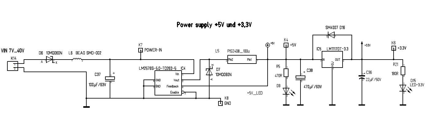
we use the LM2576-5.0 with VIN = 24VDC and the ILoad is now min. 27mA and max 50mA.

Now we could not found the minimum Load Current in the DataSheet Document.

We only found the Test circuits with 0,5 <= ILoad<=3A.

My Question: Works the LM2576-5.0 correct with 27mA and 50mA?

Is the Load with 27mA and 50mA enough?

Thanks and best regards

Stefan Balck

  • This device should work correctly with a 27mA load.  If you wish, send us your schematic and PCB layout and we will look at it.

  • Hello Frank, thanks for your fast reply.

    This is the schematic from our Power supply we are using. We connect an external AC/DC Power supply with 24VDc Output at the K14 Connector.

    After the LM2576-5.0 we generate with the LM1117T-3.3  a 3,3 Voltage Supply.

    I hope you can say that the schematic is correct an they works with minimum ILoad between 27mA and 50mA.

    Thanks and best Regard

    Stefan

  • It seems OK to me.  I assume you used the data sheet guidelines when designing your circuit.  The layout is critical to the design of

    a switcher.  When you have a PCB layout ready, we will be happy to look at it.

  •  

    Hi Frank,

    thanks for your answer.

    The image above is the PCB part of the Power Supply with the IC10 as LM2576-5.0 and IC12 as LM1117-3.3.

    We use a 4 layer PCB with there is the Top and Bottom Copper area GND. The one inner Layer is a 3.3V,  the other inner Layer is GND.

    The most parts are SMD, the Power In Connector is THT.


    Best regards,

    Stefan Balck


  • I do not see the power inductor and diode; I hope it is not L11 and D10.  If so, they need to move closer to the device.

    The SW trace needs to be short and the grounds of the output cap and diode need to be close together

  • Ok. I will do an redesign of the Power Supply Layout.
    I set the position of the Power inductor, Diode and Output Cap near the LM2576-5.0.
    If i'm ready with that, i send you the revised Layout to take a look at it.

    Best regards,
    Stefan