This thread has been locked.

If you have a related question, please click the "Ask a related question" button in the top right corner. The newly created question will be automatically linked to this question.

TPS51716 operating in low Frequency

Other Parts Discussed in Thread: TPS51716

Hi 

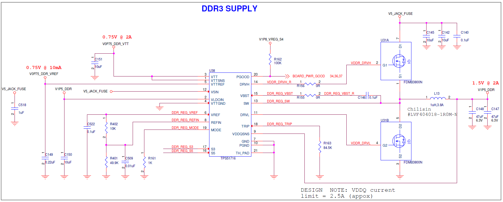
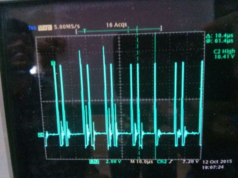
      We designed a TPS51716 circuit for DDR3 with operating frequency 500KHz. (Vin=5V; Vout=1.5V, Iout=2A) . But the switching frequency observed is 96.15 KHz (10.4uS) and 3308 KHz (4.2uS) . Rmode resistor used is 1K. Can you please help us to resolve it? 

Circut Diagram

Upper FET gate signal

Thanks and regards 

   Sebastian V P

  • looks like you are operating in pulse skipping eco-mode. That will cause the apparent switching frequency to decrease. What happens when you increase the load?
  • Hi John Tucker,
    Frequency varies even with load current 1A. Max frequency achieved is 300KHz .
    Thanks
    Seb
  • You are pretty close to the minimum Cout.  With derating you may be below it.  Can you try adding an additional 47 uF capacitor to the output?  Otherwise we made need to look at your layout.  Also can I see the SW node waveform with additional load?  Pleas be sure you are in CCM operation.

  • Hi John Tucker
              Max switching frequency reached to 403KHz on adding additional 47uF (ie Cout= 3x47uF) with less load current itself.
    Additional cap is removed (ie Cout= 2x47uF) and system loaded to output current more than 1.1A , now the switching frequency reached to 500KHz.
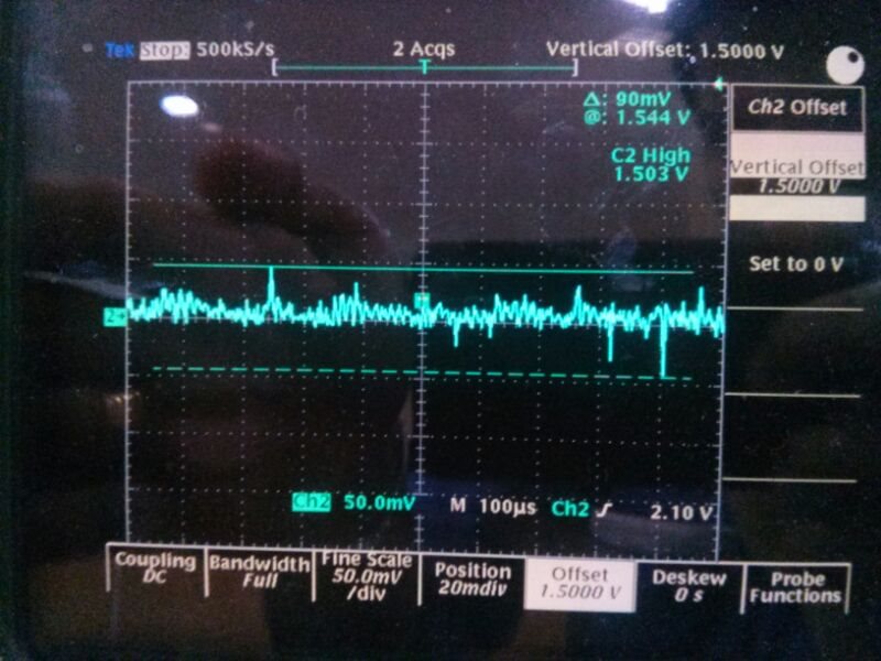
    But it is changing dynamically depend on the load current variation . Output waveform is not clean. Change in frequency could be the reason.
    Is there any way to clean the output ?
    Will it help if the frequency is constant ? Is there any way to avoid the pulse skipping option ?

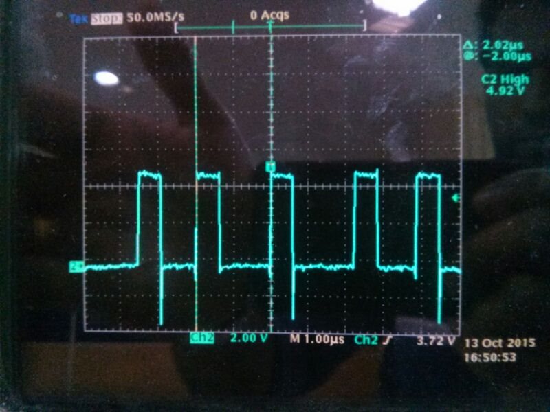
    SW node with load current more than 1A

    Output waveform ( Cout= 2x47uF)  Vertical offset (1.5V)

    Thanks and regards

       Seb

  • The DCM/CCM boundary is about 1.05 A. Below that current you should see the switching frequency decrease. Try raising the output current above 2A or more. If you maximum load current is lower than 4A, you may need to re-size your inductor.
  • Hi John Tucker,
    Our Max current requirement is only 2A. Can you suggest inductor value for this ?
    Can you look into the trip settings also for the same
    Thanks and regards
    Sebastian V P
  • ripple current for the inductor should be 0.25 to 0.5 of Iout max. so maybe 3.3uH (I have that equation memorized). You can calculate the new trip setting from the datasheet equation.
  • Hi John Tucker,

          Considered ripple current =  0.32 times of Iout( max ) to get 3.3uH inductor . Now the CCM current level will be 0.320A

    Cap changed to 4x47uF= 188uF

           Rtrip Value Changed to 27.7K to set the IOCL = 1A ( for testing the OCP)

    Following are the observations ( refer the image )

    1. Frequency Switching between 444KHz  ( 2.25uS) and 595KHz  (1.68uS) 
    2. Maximum current observed is 1.32A instead of the OCL set value 1A
    3. Same time the voltage dropped to 1.106V and it came back to 1.5V after 461.uS Instead of turning of the controller. 

    Can you please  review our calculation and comment ?

    Thanks 

        Seb