This thread has been locked.

If you have a related question, please click the "Ask a related question" button in the top right corner. The newly created question will be automatically linked to this question.

BQ24650 - Integration Problems

Other Parts Discussed in Thread: BQ24650

Hello All,

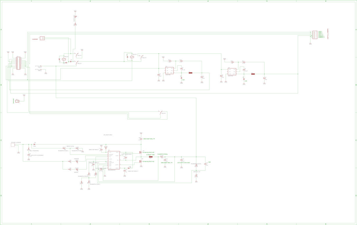
I attempted to design in a charger circuit for our 19.2V (6S2P) 6000ma/h battery packs.  We currently use a desktop off the shelf charger to do this running 22.2V max 4A.  The idea is to build the charger into our PCB using the BQ24650 for various reasons I wont get into.

We want to charge at 22.2V max 1A using this circuit, and of course the 1A would reduce if the MPPSET falls below 23.5 VDC (as set in our case).

Our supply voltage is a max of 28VDC without load.

When the Vin has power applied, battery unplugged, it draws 5ma and stat1 is low, stat2 is high, indicting a charge in progress. 

When the Battery is plugged in, no change....stat1 is low showing a charge in progress but still only drawing 5ma. 

The voltages I read on the pins with the battery plugged in are:

VREF: 3.297V

MPPSET: 1.94V

REGN: 5.95V

HIDRV 19.7V (the scope shows some PWM here)

PH 19.7V (which is the battery voltage level plugged into the circuit or unplugged

LODRV 0V (no PWM)

SRP/SRM 19.7ish VOLTS too close to read the difference using my multimeter

VFB 1.873V

I can scope a pwm like shape on the HI side mosfet Source pin around 19.7V and after the inductor a nice smooth 19.7V.

Anyways it is just not sending any sort of charge into the battery.  I waited much past the 30 min 1/10 charge recharge phase, but not different, just the 5ma most likely for the lit up LED.   Any idea what the issue could be?

Thanks in advance,

Jeff

  • Hi Jeff,

    Is there a thermistor being used in the TS pin? The proper resistor values for TS/VREF pins must be used according to the thermistor datasheet and the formulas provided in the bq24650 datasheet (Pages 16-17). R10 is not needed.

    I noticed that the battery regulation voltage is above 19.2V (19.7V according to your readings), if you want to be closer to 19.2V, you should lower R11 (243k ohm gives around 19.1V).

    All capacitors should have a voltage rating higher than what is expected, I recommend 35V to make sure everything works.

    Go over the Application notes on the datasheet (pages 21 to 25) and look for any differences with your design. Look at the PCB layout recommendations.

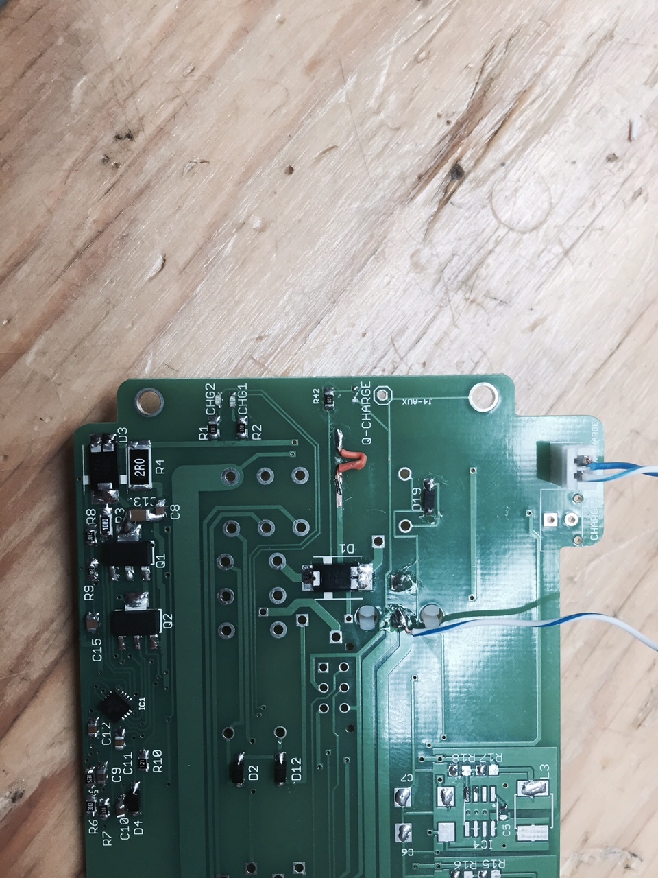
    Also, I suggest giving a closer look if the soldering is good, everything making contact correctly, and that there is no shorting.

    Thanks,
    Steven
  • Hello,

    No thermistor, I use the 10K to ground to trick the bq24650.  Voltage on TS pin is 1.9V which is within the OK range for a charge to commence.

    All caps 35V or more.

    Soldered a 2nd board, with exact same results.

    The nominal voltage of this battery pack is 19.2V, but they charge now with a 22.2V quick-charger 4A.  There is a little BMS inside the pack, but it should accept the charge from this BQ24650.  Additionally, the BQ24650 is showing a charge status LED while no battery is even plugged in, so I think the issue is unrelated to the battery pack.

    TI has a evaluation board (BQ24650EVM) with a few extra caps & diode in it , so I tried adding these and no change. (4.3 BQ24650EVM schematic added C1, D3, C11, C12, C3) 

    Running out of ideas and patience here.  TI techs not helping and seem to be leaving these issues to the gen-population to figure out.

    JL

  • Jeff,

    The bq24650 is very sensitive to board layout. MOSFETS and passive components should be closer to the IC to reduce copper trace.

    I recommend working with our EVM which has been tested to work. You can make your modifications on our EVM and integrate it to your system to see if the concept works. Link to our EVM: www.ti.com/.../bq24650evm-639

    You can also look at how our EVM PCB layout is done. Check the user guide for the EVM: www.ti.com/.../sluu444a.pdf

    When you are sure that your concept works with your system and our EVM, I suggest reading page 25 of bq24650 datasheet and recommend that it is a 4 layer PCB.

    As for the inductor, sense resistor and output capacitor, I recommend using 6.8uH, 10mOhm and 20uF respectively. These ensure the best scenario for 4A charging.

    I recommend that the TS pin have R5 = 6.8k and R7 = 10k. Remove R6 and R10. You want to be as close to 60% from VREF so that TS is tricked.

    Thanks,
    Steven