


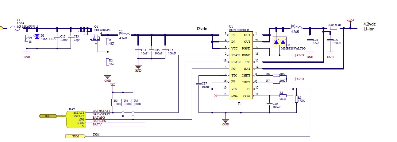
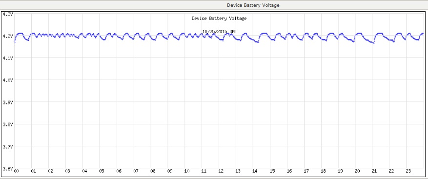
I have a circuit that models the reference design we are having problems with. We are trying to identify if the problem is design or manufacturing or components but don't understand the operations that are occurring. In this circuit it appears as if the charger is going on and off all the time well above the expected thresholds.
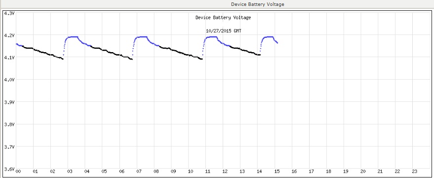
In an operational unit the output waveform on charger looks normal, the voltages goes up to 4.2 the charger turns off and it decays until the 4.1v threshold. In the bad unit (same circuit) the output decays only slightly and the charger starts to charge again. I have probed the circuit with the scope and don't see any ripple in the input or output that would cause this. Can you give me some ideas? In the bad circuit I have put 3 different battery cells and the results are the same so it doesn't seem like a cell problem. The thermistor in the circuit is in the battery pack and the voltage levels seem correct so we are not sure what is causing the charger to start up so soon. the circuit pulls a battery measurement every 1 minute and then is smoothed slightly to display the curve.
expected waveform:

charger circuit
