This thread has been locked.

If you have a related question, please click the "Ask a related question" button in the top right corner. The newly created question will be automatically linked to this question.

LMZ14201 failures

Other Parts Discussed in Thread: LMZ14201

Dear Sirs, 

I use the part LMZ14201 in a design to convert from +24V input to +4V ouput and from +24V input to -4V ouput. The positive regulator schematic is the one recommend at the part datasheet. The negative regulator schematic is the one recommended in the application note AN-2027. From a series of 46 boards (92 regulators) I got 5 failures, 3 failures in the positive regulator and 2 in the negative regulator. The failure mode is that the ouput remains near zero volts. When the parts are replaced (desoldering the failing regulator and soldering a new one) the problem is solved. I have some questions related to this failures:

Can you inform me about the possible reasons of such failures?

Best regards, 

Gustavo Martínez


  • Please send us your schematic and a capture of your PCB layout.

  •    Please, find attached a pdf containing schematic and PCB layout capture

    Simple_switchers.pdf

  • Gustavo,

    What is your solder reflow profile? Specifically, what is the maximum temperature and how many reflows are your boards going through? Can you also share your PCB layout document? in does not matter which tool as long as you specify the name to us. We are still evaluating your schematic and would like to have that extra piece of information. 

    Thanks,
    Anston

  • Your schematic looks okay. My only recommendation is to add a 100uF capacitor on the input supply of the negative rail connected to system GND. I have a feeling it is your reflow profile or PCB layout. I cannot see your layout very clearly in the image especially for FB and VIN of both positive and negative sections.

    Thanks,
    Anston
  •     Please, find attached the reflow profile of the board. I think it is ok but please, let me know your opinion. 

        To me, it looks strange that a bad layout can make fail only some devices, but may be possible.

        In addittion, I wonder about the storage, it is any special recomendation for the storage of these devices. They are stored

        inside their bag in a metallic cabinet under normal levels of temperature and humidity.

        I also wonder about electrostatic discharge, do you think an ESD problem could make the part fail?


        Thank you, best regardsswitcher_board_REFLOW.pdf     

  • Gustavo,

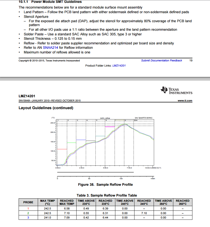
    The failures you are seeing are directly related to the solder reflow process you are using. These modules in the datasheet are required to never cross 245C. If they do, they will damage the module. It would directly explain why you are seeing a small batch of failures.

    Please refer to the instructions in the datasheet to limit the solder reflow temperature to a max of 243C to keep some margin from 245C.

    Attached is a screenshot of the datasheet solder reflow instructions:

    Thanks,

    Anston