


Hi!
I already used TPS22960 in previous projects and it works fine.
Now I am working in a project wich has a lot ov restrictions about board space and use of MCU pins (and I have to switch about 15 loads).
Due to this, I itend to migrate from TPS22960 to TPS22994. And I intend to use I2C interface only (no GPIO On/Off control).
In my application, on cold boot I have to start with all power outputs switched to OFF.
Firmware logic will turn power outputs ON as needed.
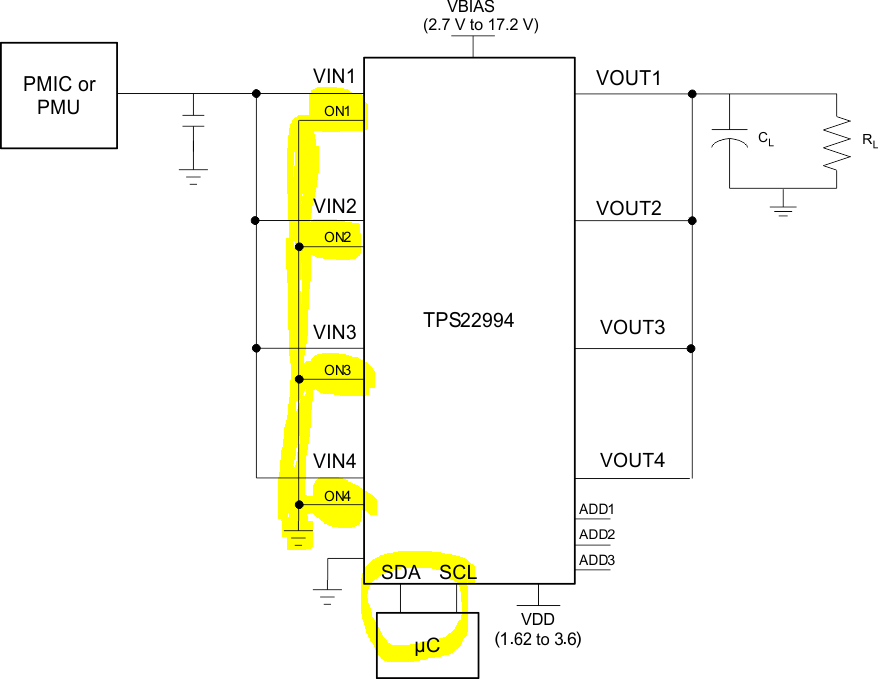
So, my question is if is the schematic below valid for the operation described above (I still able to program internal IC registers, even if I tie all ONx inputs to GND, correct?).
Thanks in advance.
Wagner Coimbra
