This thread has been locked.

If you have a related question, please click the "Ask a related question" button in the top right corner. The newly created question will be automatically linked to this question.

LM3150 Unstable Frequency

Other Parts Discussed in Thread: LM3150

Hello,

We have problem with unstable frequency on SW pin (please, see attached video).

On one large PCB (333mmx333mm) are 3 identical power supply and all have same problem with frequency instability.

Cff do not have any influence on instability. I tried values from 100pF to 1n (calculation says 255pF, populated 330p). Nothing happens (not even worse).

Power supply setup:

  • Vin=18V,
  • Vout=3V to 5V (PWM regulated from uC)
  • max current up to 5A,
  • 4L PCB,
  • C1 and C2 are populated (tantalum capacitor 330uF)

Schematic:

 Video file:


  • Hi Kreso,

    Thanks for the question! We received your schematics and video files and are reviewing them now. We'll have something to report back soon. 

    Thanks,

    Anston

  • Hi Kreso,

    Do you observe the instability throughout the load range, or is there a window where the switching becomes unstable? Please can you also send us a plot of the inductor current along with the switch node?

    We are modifying our existing EVM according to your schematic and will try replicate the issue on bench.

    Best Regards,

    Doyel

  • I will send plot of the inductor current along with the switch node soon.
    Instability is not in some window it is more like linear behavior .... larger current -> larger instability. Some power supplies are very instabile over all load range from 100mA (minimal possible load) to 5A.
    Regards
  • Hi

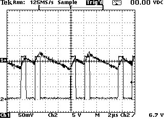
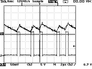
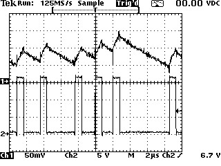
    I made plot of inductor current with SW pin. To do that resistor 25mR (shunt) was soldered in serial with inductor. One probe (CH1) measure voltage across that shunt, and another (CH2) SW pin. Oscilloscope (THS730A) have 2 isolated channels .

    This power supply is the worsted (with most frequency instability).

    Input voltage supply: 18V

    Output voltage: 3.7V

    load -> 628mA

    load-> 2.5A

    load -> 4.2A

    Video file showes instability on three loads (600mA, 2.5A and 4.2A):

  • Hi

    Same power supply but without tantalum capacitors (2x330uF/10V) on output frequency instability is less. Unfortunately this solution is not adequate because power supply supplies large number (108) of IC including uC and every IC have bypass capacitor (1uF and 100nF plus internal parasite IC capacitor) so power on current  is 15A for ~1us and without tantalum capacitors voltage drops from 3.8V below 2.2V. Watchdog reset uC when voltage drops below 2.5V. So on every power up uC is reseting. Off course, uC controls other circuits so I have chain reaction on all board. 

    Frequency "dancing" don't bothered me. Output voltage is very stable with tantalum capacitors. I am concerned with question: Can that behavior harm to LM3150 or transistors? How it acts on long time behavior?

    I tried 20 power supplies in environmental chamber on temperatures from -40°C up to +80°C. Output voltage was stable, could start OK, working on full load (4.2A) and minimum load (620mA) OK. Let say without oscilloscope I would never suspect that is something wrong.

  • Hi Kreso,

    Sorry for the delay in response; we are still looking into this and will get back to you as soon as possible.

    Regards,
    Doyel
  • Anything so far?
  • Hi Kreso,

    Because the LM3150 is a Constant On Time controller, the converter's behavior is close to that of a hysteretic system and so can be subject to some frequency instability if the signal at the FB pin has low ripple since the next cycle will be triggered only when the FB voltage falls below the reference and not due to a fixed oscillator.

    Frequency instability is indesirable but it should not be an issue for the converter or the FETs survival as long as the overall averaged frequency is reasonable (for switching losses considerations).

    One way to remediate the instability, beyond increasing the actual output voltage ripple, would be to inject a AC signal at the FB pin sensed at the inductor level.

    The following article details the various compensation solutions for COT to address this type of issue:

    http://www.wirelessdesignmag.com/article/2014/07/simplifying-wide-input-voltage-dc-dc-converter-design-cot-topology

    You might want to try the scheme shown in Fig.8 of that article.

    I hope this helps,

    Florent Boico

  • Thank you for reply. It could be that the ripple on fb pin is to low. What is the mimimum peak to peak voltage on fb pin? I have 50mV.....as you can see from oscilloscope plots.