This thread has been locked.

If you have a related question, please click the "Ask a related question" button in the top right corner. The newly created question will be automatically linked to this question.

DCR012405U Regulated DC/DC Converters

Other Parts Discussed in Thread: DCR012405

Hi Sir/Mdm,

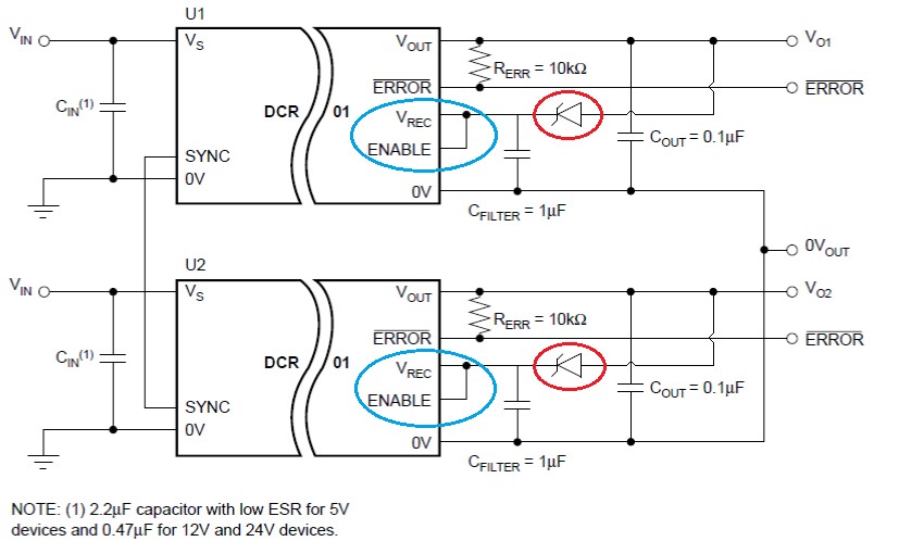
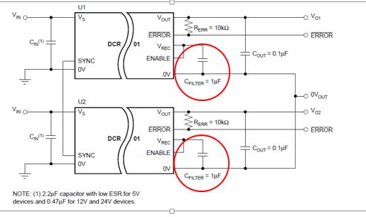
For Texas Instrument DCR012405U Regulated DC/DC Converters, what is the recommended Cfilter for the rectified (Vrec) output?

Any particular MPN, type, size, besides the recommended capacitance?

Regard's

Jason

  • Vrec Cfilter required filter  capacitor type , value/  is a 1µF ceramic capacitor. The capacitor body size can be 0805 or 1206  16 volt rating . Ceramic capacitor tolerance recommended is X5R. Ceramic capacitors have a very low ESR ( equivalent Series Resistance ) at these switching frequencies of  2-10milliohms.

    1µF ceramic capacitors are very common and available from numerous distributors or vendors.

    Tom

  • Hi Tom,

    Thanks for the advise. Would like to ask another 2 question as below.

    1. What is the Absolute Max Voltage between Vrec and Vout (Vds of the LDO regulator transistor)?
    2. Can you tell us what is the Max Vpp of Vrec to 0vout (without filtering)?

    Regard's
    Jason
  • Jason:

    1. The typical DC voltage across the linear regulator Vrec to Vout  is about 9V.

    2. Typical P-P Square wave pulse is about 20V P-P.

    Tom

  • Jason:

    1. The typical DC voltage across the linear regulator Vrec to Vout  is about 9V.

    2. Typical P-P Square wave pulse is about 20V AC  P-P with no Vrec 1uF ceramic capacitor.

    Tom

  • Hi Tom,

    We need these information to ensure reliability in any possible failure mode.

    1. Is there a need for additional protection for the LDO Vds from excessive voltage and negative bias - Vrec and Vout (Vds of the LDO regulator transistor)?

    1.1 Estimating zener clamping at about 12V, given typical is 9V, sufficient?

    1.2 What is the maximum negative bias tolerable, estimating a zener Vf of 0.8-1V, sufficient?

    2. Is there a need for additional protection for Enable from voltage transient/spike (during power up, between Vrec and 0Vout) given Enable is connected to Vrec?

    2.1 Is Enable a logic gate or does it power vref/error amp/ etc etc or both?


    Regarding:

    “2.     Can you tell us what is the Max Vpp of Vrec to 0vout (without filtering)?

    Ans: Typical P-P Square wave pulse is about 20V AC  P-P with no Vrec 1uF ceramic capacitor.”


    Thus, the typical voltage that will be seen at Vrec to 0vout after full wave rectification will be about 10VDC (assuming no switching loss) with minor square wave oscillation. Is this correct?


  • Jason:

    The DCR012405 or  linear regulator (LDO) does no have over-voltage protection. The LDO does not have negative voltage protection.  DCR012405  absolute maximum input voltage is 29V.  If there are any transients above this limit, a transient suppressor is required on the input bus.

    What is the DCR012405U end application? Is it  a motor drive or does it have secondary voltage exceeding 60VDC or 42VAC?

    Any further questions or comments can be sent to me at tguerin@ti.com

    Tom