This thread has been locked.

If you have a related question, please click the "Ask a related question" button in the top right corner. The newly created question will be automatically linked to this question.

How to wire up flyback transformer with multiple windings

Other Parts Discussed in Thread: LM2586, LM5118

Hello all,

I'm using the Workbench to design a 14V flyback switching regulator. The design can be found at http://webench.ti.com/appinfo/webench/scripts/SDP.cgi?ID=258A678DA273F45E

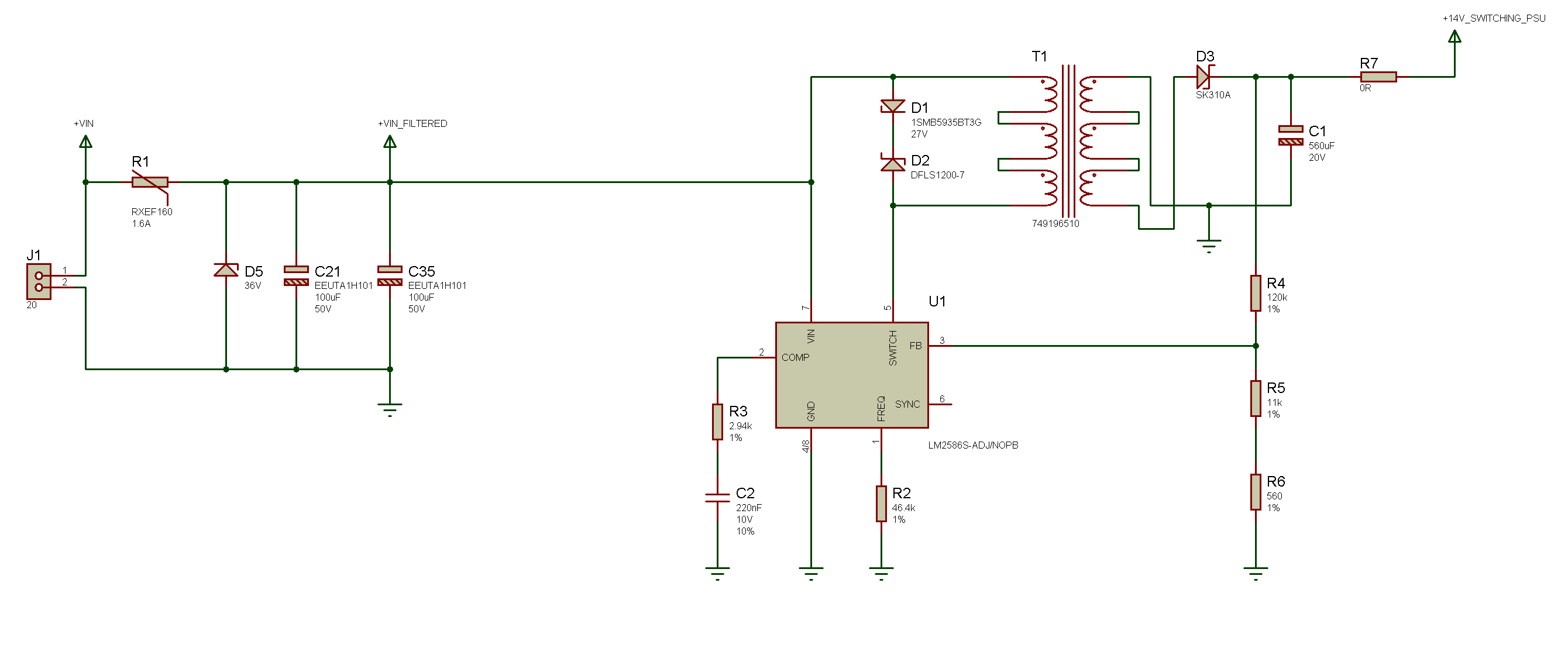
The transformer recommended by Workbench, the Wurth 749196510 () has 3 primary and 3 secondary windings. 

Am I correct in saying that the transformer should be wired with the 3 primary windings in series and the 3 secondary windings in series? i.e. like the following:

  • Hi Amr,

    This is most peculiar. The inductor you were suggested is a little overkill for the application. I suggest using a simple 1:1 transformer instead of the webench recommended part. Ensure the inductance is at least 89uH.

    I have pushed this question to the Webench group to take a look at and see how or why this inductor was recommended to you.

    Thanks,
    Anston
  • Hi Anston,

    Thanks very much for your response. I'll see if I can have a look for an alternative part.

    Unlike for some of the other TI switching power supply controllers, the datasheet for the LM2586 is very sparse and doesn't contain any information on how to go through the component selection process (contrast this with the LM5118 which I've successfully used in the past!).

    When selecting an alternative for the transformer suggested by Workbench, other than the inductance, what other properties should I watch out for? Here are the parameters I think are important:
    - Inductance at least 89uH
    - 1:1 turns ratio
    - Saturation current of primary and secondary to be at least 2.2A (based on the maximum current reported by the simulation for the input and output currents at the different input voltages I'm expecting to use the device).

    Is there anything else I need to watch out for?

    Also, I've noticed that many distributors have a separate category for "coupled inductors", which seem to be very similar to the flyback transformers. Could these be used, assuming the critical parameters I listed above (plus any others that you might add) are met?

    Thanks,

    Amr
  • Hi Amr,

    All the parameters you listed are important and adequate, I would add DCR of the inductor as a consideration to help efficiency.

    Coupled Inductors and Flyback transformers are both forms of transformers, however with different manufacturers, isolation voltage/current tends to be what set them apart as two separate categories or the same.

    Thanks,
    Anston
  • Hi Anston,

    Thanks once again for your reply. Based on the Workbench simulation, I believe that these are the critical values of the transformer:

    • Inductance: 89uH
    • Windings 1:1
    • Isat: 2.25A (based on the maximum current in the primary winding at 10V input using the workbench simulation).
    • Irms: 1.65A (based on me working out the RMS of the current waveform at the primary at 10V input from the workbench simulation).

    Based on my understanding of the parameters of coupled inductors, in order to try and find an equivalent one, I searched for the following parameters:

    • Parallel Inductance: > 89uH
    • Parallel Isat: > 2.25A
    • Parallel Irms: > 3.3A (1.65A * 2, since I will be only using one of the windings, hence half the parallel Irms)

    Unfortunately, I wasn't able to find any coupled inductors that would meet those specifications. This led me back to having a look at transformers. You mentioned that the transformer recommended by the Workbench (the Wurth 749196510) was overkill for this application. Looking at the datasheet for the part, and assuming that I would wire it up so that the each primary and secondary windings are in series, these are the specifications of the part:

    • Inductance: 89.1uH (9.9uH/winding, 3 windings in series therefore 9.9 * 3^2 = 89.1)
    • Isat: 3.51A (1.17A sat current/winding, 3 windings in series therefore 1.17 * 3 = 3.51)
    • Irms: 1.91A (Even though I'm using three windings, they are in series, so that rms current won't change).

    Comparing the transformer specs with my critical values listed above, it doesn't seem too over the top. The Isat is quite a bit higher than required, but it seems like a reasonable safety margin.

    Is my understanding regarding the critical transformer parameters and the interpretation of the transformer datasheet correct? What factors made you come to the conclusion that the transformer was over-specified?

    Thanks,

    Amr

  • Hi Amr,

    There is nothing wrong with the approach you suggested. You can proceed to tie the windings in series and get the required inductance and current rating. However, this is the first time I've encountered needing to do this. There are usually coupled inductors available for most applications. This application is a little more unique and this might be the best option.

    Your understanding of the specs is correct.

    Thanks,
    Anston