This thread has been locked.

If you have a related question, please click the "Ask a related question" button in the top right corner. The newly created question will be automatically linked to this question.

BQ40Z60 New hardware: CHG_FET on, DSG_FET off so no battery action

Other Parts Discussed in Thread: BQ40Z60, BQSTUDIO

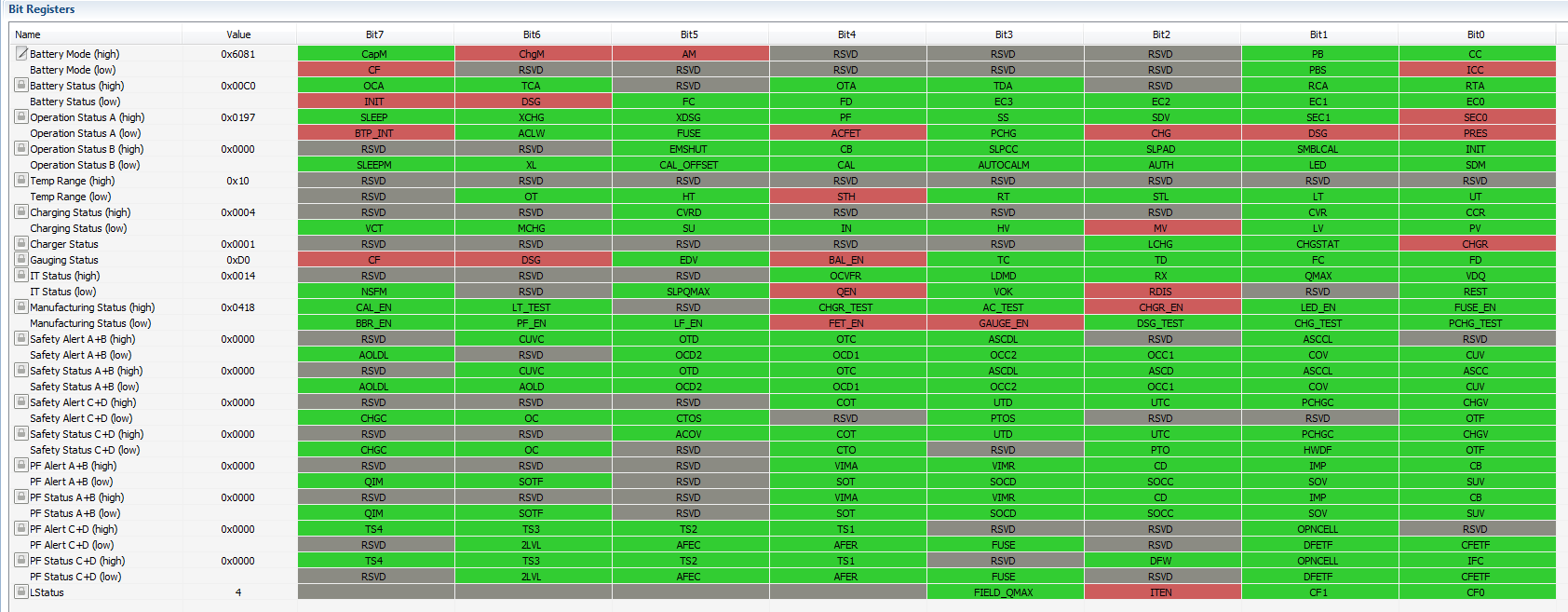
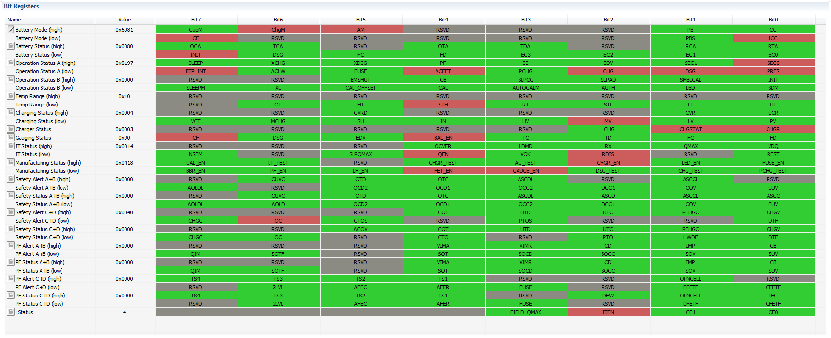
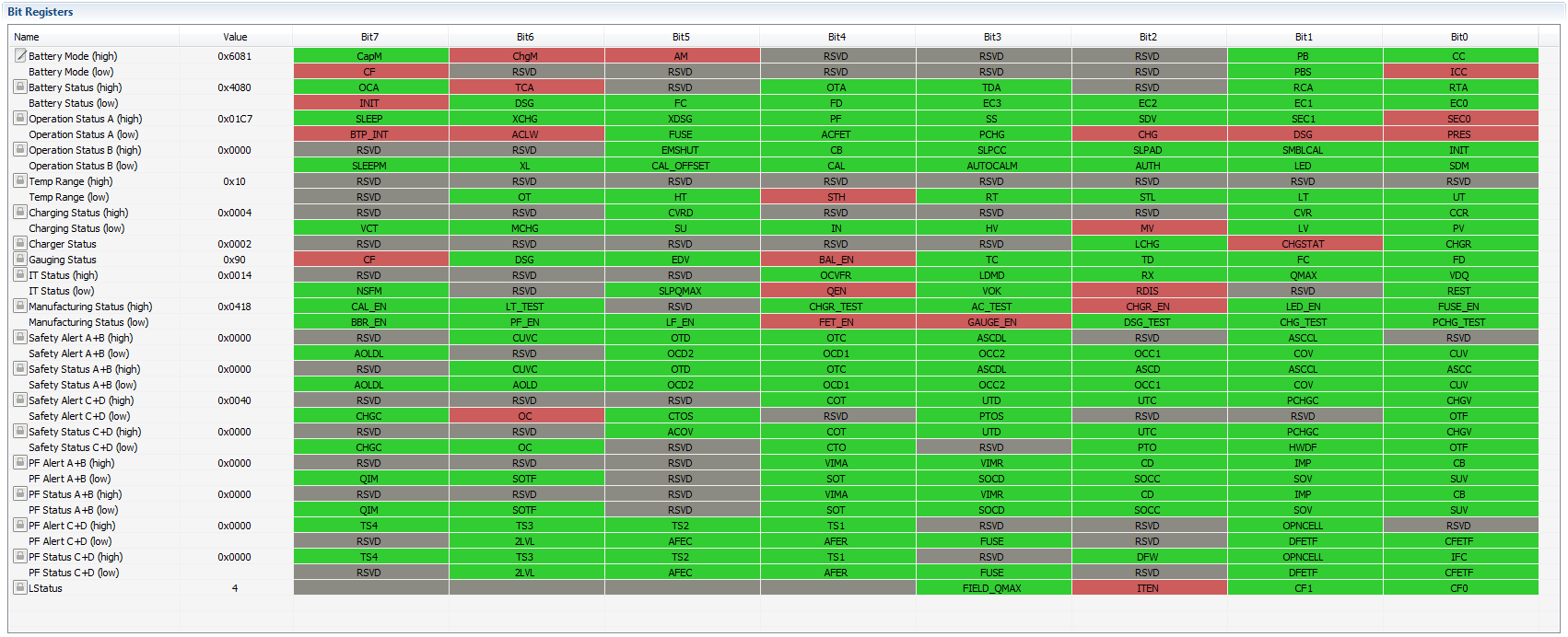
My new hardware design is identical to the EVM and recommended application circuit in the BQ40Z60 data sheet.  Specifically, the battery pack output feeds the CHG_FET and DSG_FET and then it's off to VSYS, feeding the load.  Unfortunately only CHG_FET is driven ON with the batteries installed.  Is this the default condition?  It seems more like a fault.

I can talk to the device through the SMB channel and have set NR high (red) and have also programmed the chemistry.  FWIW I can turn on the charger FET's manually.

  • I need to know if the device, by default comes up with CHG_FET and DSG_FET on, or if there's a need to program the device to do so. This is not clear in the data sheet or technical guide. TI?
  • There is a FET Enable command (22) to turn on the FETs. There is information on the FET_EN in the TRM and EVM User's Guide.

  • Tom, I'm aware of the commands.

    My question posted was: "I need to know if the device, by default comes up with CHG_FET and DSG_FET on, or if there's a need to program the device to do so. This is not clear in the data sheet or technical guide."

    What are the programmed defaults for the BQ40Z60? 

  • You can set bits in the Mfg Status Init register to enable features automatically when the data flash is programmed with your configuration. You can set the FETs to enable. We do not recommend that Gauging, PF faults or Lifetime data to be set to start automatically. The pack should be calibrated first.
  • Thank you.

    Is there a listing somewhere of what comes up on the device in the un-programmed state?
  • None of the enable features in the Manufacturing Status register are enabled in the default configuration. The 1st level protection features will be active, but the FETs are turned off so a fault will just set a Safety Status flag.
  • Thomas. The design is working, to a point. Thanks for the support so far.

    Next: Another problem with the CHG and DSC FET's

    With batteries installed (4x18650) both CHG and DSC FET's remain OFF. They turn on when the DC adapter voltage is applied. And, when the DC adapter voltage is removed, the FET's stay ON. Is there a means to have these FET's ON when batteries alone are installed?
  • When you were running off of the batteries, was the device running an communicating or was it in shutdown? You have to apply a charging voltage to wake-up the device and it should turn the FETs on as long as the FET_EN is set and PRES is lit. The charging voltage is only required to wake-up the device and it should run off of the cells after that. If you can send a screenshot of the bqStudio registers screen, then I may see another problem that is keeping the FETs off.
  • The CHG and DSG fets only turn on when the charger is connected first.  Once I do this, and turn on the batteries (installed switch at fuse), they stay on even when the charger is disconnected.  Ideally, I want them to turn on when the batteries are installed.  However, there may be some utility it requiring a charger connection when batteries are replaced in the field.

    I can get screen shots starting with charger only as just batteries does nothing (although I see BAT has battery voltage DC on it)

    1. Charger no battery:

    Charger with battery:

    Battery with charger disconnected:

    I'd send you a schematic but can't make this public.  How can this be accommodated?

  • Voltage has to be applied to the VACP input to wake the device up from shutdown. Attaching the cells will not do this. You will either need to apply the charger or some other shunt to apply a temporary voltage to VACP to wake the device the first time.
  • Would it be "legal" to apply battery pack voltage (sorry, reduced to appropriate limit, of course) to this pin?  This way, whether from the charger or pack, it gets its wake up call?

  • Yes, that would work. We have a pushbutton switch that applies the BAT voltage to the VCAP pin to wake up the device.
  • OK. But in terms of functional requirements of the BQ40Z60, does applying a voltage to this VAC pin indicate to the device that a charger is connected and therefore sets the device into a certain mode?

    Also, use of a button indicates an intermittent signal. I'd prefer to simply run the battery pack voltage through a diode (followed by 10K) to the pin, and leave the charger voltage (also feeding this same pin) in place, although could simulate through a 1-shot. If the device needs to distinguish VAC versus VPACK then this won't do, correct?

    So, how to "wake up" without user pushbutton intervention as a function of either plugging in the charger, or installing the batteries?
  • The device should go to Normal mode after it wakes up. You should be able to apply the BAT voltage to the VACP pin through a diode and resistor to wake it up. The gauge will report an AC Adapter voltage present continuously.
  • OK Tom.  I think we'll use the default behaviour and require connection of charger to bring unit to life after battery install.  In a production setting there's no problem.  The concern is field battery replacement for which a procedure will be written.

    Thanks for clarifying.