This thread has been locked.

If you have a related question, please click the "Ask a related question" button in the top right corner. The newly created question will be automatically linked to this question.

TLC59116IPWR EFLAGs not working as documented?

Other Parts Discussed in Thread: TLC59116

I have a set of  4-year-old TLC59116IPWR parts. In case it's a known problem that has since been fixed, I've ordered a couple samples.

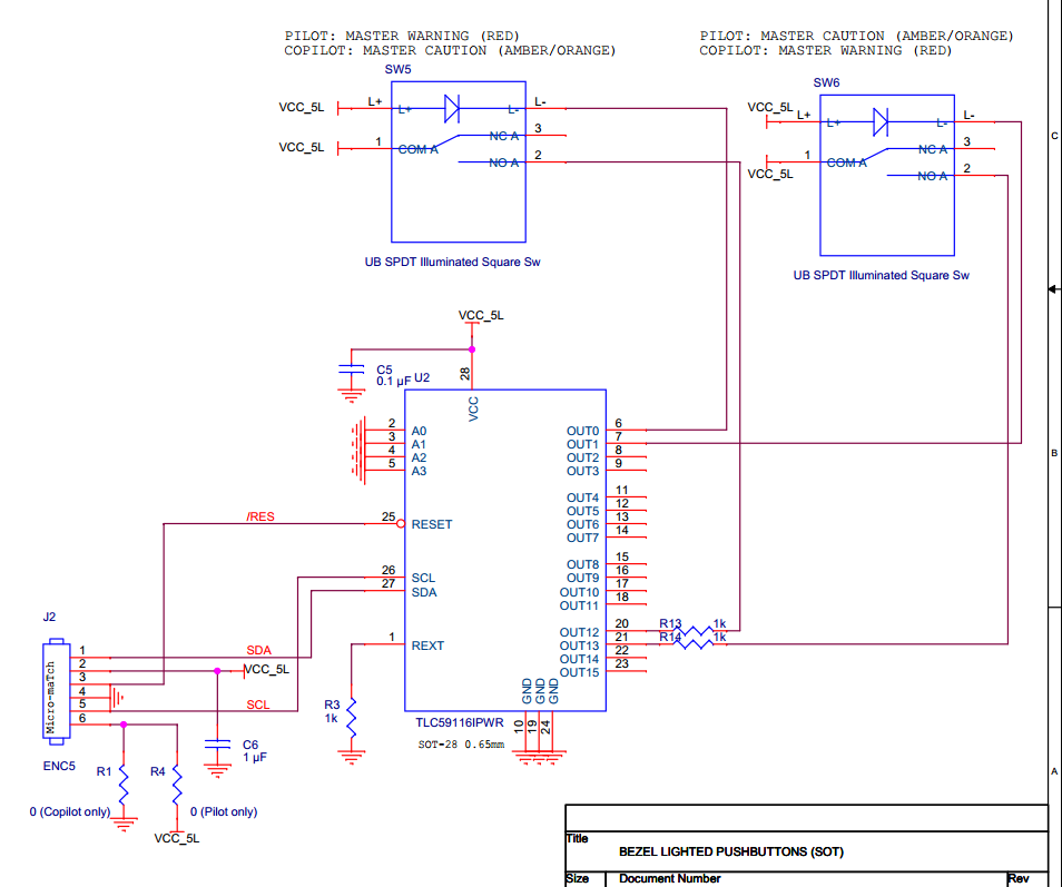
The situation is a bit odd: I've got some lighted pushbuttons in a cramped space and limited budget, mounted remotely from the main board (by "remotely" I'm talking about inches, not miles :). So I want to drive LEDs, read button presses, and control it across a small cable. It occurred to me that the TLC59116 could either drive a multiplex circuit or I could use no-load error detection. I chose the latter.

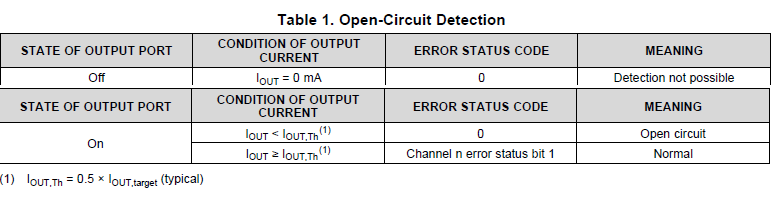
At this point my experience with the EFLAGs is that the bits are inverted (0 means error, 1 when there's a proper load). The documentation (SLDS157E –FEBRUARY 2008 –REVISED DECEMBER 2014) explicitly says that "A 1 indicates an error". See pp 12-13 and pg 21.

Rext = 1K, IREF = 0x5E, so current output should be 4.62mA. Iout,Th will be 2.31mA. I've also played with other IREF settings, the design allows brightness calibration. The buttons are connected to one output each with a series resistor, Normally Open. On currently has 330 ohms and the other has a 1K resistor; both appear to work identically.

I expected the error bits to be active (1) until I pressed a button. However, the error bits stay at 0 until I press a button, when that output's bit goes to 1. This is the opposite of how I expected them to respond, since the button not being pressed presents no load to the output.

I also have an older prototype board that has an LED on each output. That part presents a 1-bit on all "button" outputs all the time.

I guess my questions are:

  • Is this something I'm doing wrong, or a flaw?
  • Is it a flaw in the part, or in the documentation?
  • If in the part, is it just my (older) parts?
  • If in all parts, is this a known issue?
    • If it's a known issue, is it scheduled for correction? (Because if it isn't, then that means it's actually a flaw in the documentation. Technically.)

I don't care whether the bits are active-high or active-low. I can program around either one. (Or since the buttons are SPDT, I can design the wiring around either one. Win-win!) (And I just now double-checked. I am indeed wired to the N.O. terminal.) I just need it to be predictable.

For the record, aside from the error flags being inverted, my prototype appears to be working very nicely. The pushbutton detection is transparent. I will probably go to production with this design.

  • Hi Jeffrey,

    My name is Harry Kennedy, and I can help you with this issue.

    Just to clarify, you're using a single TLC59116 device. on some of the outputs, you're using LEDs and the other outputs are push buttons. Your goal is to read the error flag to determine when a button is being pushed correct?

    One more question, are the buttons being connected to a 5V rail or is the voltage different?
  • Two outputs are LEDs, two outputs are Normally Open pushbuttons, with series resistors. All are tied to the 5v rail.

  • ...And that is correct, I'm trying to determine button presses by reading the error bits.
  • Oh, right. Human social interaction. Protocols and stuff. :) Hi Harry, thanks for taking time to answer my question.

    ...Yeah, I'm a nerd. And I haven't had my caffeine yet. That's my excuse and I'm sticking to it.
  • Not a problem Jeff,

    I think I know what's going on, but I just want to prove something out in the lab to make sure.
  • Jeff,

    Try removing the resistors (R13 and R14). That should fix the problem. I'm working on the explanation.
  • If I do that, then pressing the button causes a dead short, which is at least potentially an error. Of course it will only present as an error if the output overloads thermally. If not, then it should be an ordinary load, which should not trip an error condition.

    On the other hand, the absence of a load (less than 1/2 the target mA output) is supposed to present as an error in any case. Theoretically, switching between a no-load condition and a dead short should present as an error all the time. Of course I'm not driving the output very hard, so the thermal error may not happen at all, or may require some time before it manifests.

    Since you asked, I'll try the experiment when I return from lunch, but I don't think the results will be useful.
  • I'm getting the same results: the error bit is 0 until I press the button.

    My samples of (presumably) new TLC59116 parts have arrived. I'll solder one to a protoboard and see if it's any different.
  • The new part works the same as the old parts. Whatever it is, at least it's consistent!
  • Jeffrey,

    Took me a bit longer to see your perspective, but I understand now. Your setup is correct, and your best bet is to use Table 1 on page 12-13 as the only reference. The table on page 21 is incorrect, and I'll work to get that updated (thanks for catching that!). Turns out I was solving a different problem with asking you to remove the resistor. I overlooked that you changed the IREF register to lower the expected current output.

    I'll keep the summary I wrote below in case others have the same problem.


    Here's a description of the errors. If the channel is off, you will always return a 0 on that channel's bit in the register.

    If the channel is on however, the 0 bit represents an open circuit. Having a connection (LED or button press) will change that channel's bit to a 1, indicating normal operation.  

    In your case, the switches are normally open (according to the schematic). That means when you read the Error flag registers, the channels that have LEDs on them will show a 1, and the channels with the normally open switch will show 0. When you hold down the button and then read the register, the channel that corresponds to the pressed switch will now show a zero.

    In summary, your button press will change the channel's register bit from a 0 to a 1.

  • It does. Moreover, I didn't notice the contradiction in the document; I was depending on the table on page 21 and would have pointed out the disparity had I noticed.

    Looking back and reading the descriptions of both thermal and open errors, it seems that pp 12-13 are consistent and only page 21 is incorrect, and apparently you need only flip the bit sense on the table to fix it.

    Wish I'd noticed that, I'd simply have pointed out the consistency error and gone with what was working.

    Thanks very much for your help, I can now put this to bed.