This thread has been locked.

If you have a related question, please click the "Ask a related question" button in the top right corner. The newly created question will be automatically linked to this question.

TPS2553-1 FAULT Pin behaviour

Other Parts Discussed in Thread: TPS2553-1

Hello TI team,

we have designed in a TPS2553DBV-1 as a USB power switch in an embedded design.
Current limit is set to 500 mA by attaching a 52k3 resistor to ILIM.

Evaluating the power switch, I notice a behaviour that is in my understanding not-conformant to the datasheet.

Enabling the switch via a CPU GPIO functions correctly.
If the output is shorted to GND, current is limited to zero, and the FAULT# signal is correctly set by the IC.
After the overcurrent condition is removed, the FAULT# pin still low > correct, TPS2553DBV-1 is fault latching.
After toggling the EN pin, the switch is back with normal operation. So far so good :o)

If an overload of e.g. 4.7 R is attached to the output, current limit works correctly, resulting in a output voltage of ~2.6 V.
However, the FAULT# pin is not set, it remains high (measured with multimeter directly at pin).
From my understanding of the datasheet, the FAULT# pin should go high in overcurrent conditions. Also, the TPS2553DBV-1 should latch-off in an overcurrent condition.

Did I misunderstand something here?

Is there an error in our schematics? See attached. 

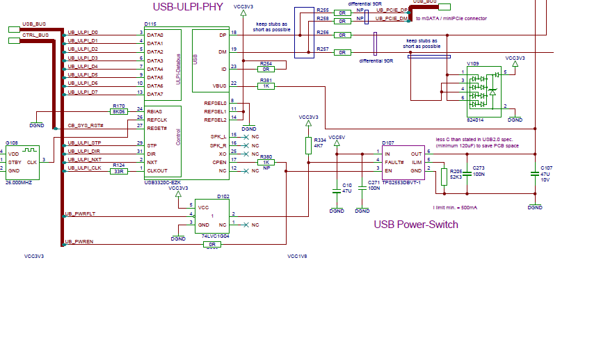
Package marking and footprint is correct, I checked.


Thanks in advance and best regards,
Stefan

  • Sorry, upon reading the question again, I noted an error:
    "From my understanding of the datasheet, the FAULT# pin should go high in overcurrent conditions."
    should be:
    "From my understanding of the datasheet, the FAULT# pin should go LOW in overcurrent conditions."
  • It seems that some on board condition has fooled the TPS2553-1 into thinking it is not in fault even though the output voltage acted as expected. It will be hard to make a determination of what is occurring without some detailed scope waveforms.

    Would it be possible to measure (using current loop) the current either into the IN pin or out of the OUT pin? 

  • Hello Eric,

    thank you for your response.

    I tried to recreate the behaviour I experienced, with shunts for current measuring in place.

    I confusedly found that the switch now works correctly.
    I persume I made a mistake at some point in my evaluation work the last time, although I am puzzled where that might have been.

    I will try with a different hardware unit at a later point of time.

    Please consider the issue solved for now.

    Sorry for creating this buzz.

    Best regards,
    Stefan