Because of the holidays, TI E2E™ design support forum responses will be delayed from Dec. 25 through Jan. 2. Thank you for your patience.

This thread has been locked.

If you have a related question, please click the "Ask a related question" button in the top right corner. The newly created question will be automatically linked to this question.

LM2676 Output

Other Parts Discussed in Thread: LM2676, LM43603, LM46002

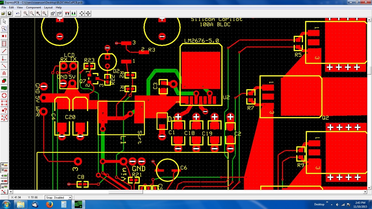
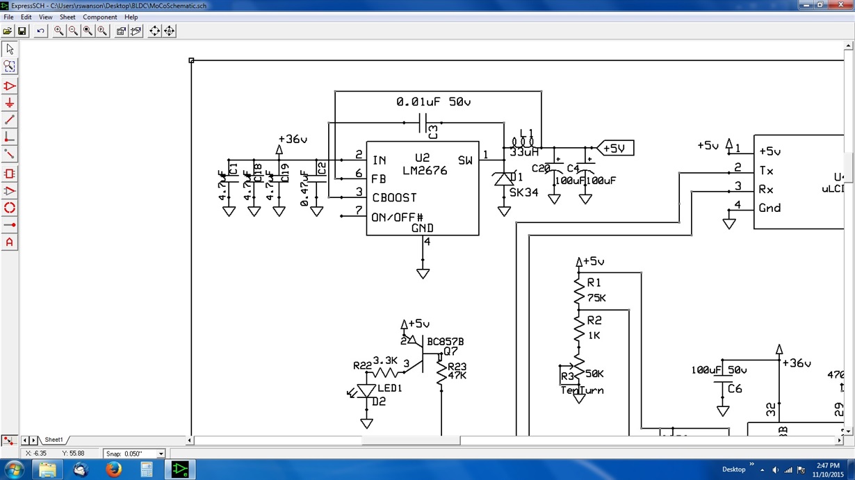
I am a first time user of the LM2676, using it on a PCB to provide 5volts at up to 2 amps.  The input voltage to the LM2676 will be 36 volts supplied by a battery pack.  I have used the data sheet nomographs and the associated design procedures resulting in the following schematic and PCB layout.

The only exceptions regarding recommended component specs were the following:

L1: Collcraft, DO3316P-333MLB, surface mount, .1 ohm DCR, 15Mhz SRF

D1: Diodes Inc., SMAZ5V1-13-F, 5.1V 1W Zener. 1.2 volts forward voltage.


Note: the following diode is on order: NXP PMEG6030ETPX, SMD, 60V, 3A (50A forward surge), 460mv forward voltage drop.  I will replace the SMAZ5V1 with this diode.

The PCB is four layers. One is a ground plane (inner layer) one is the 36volt supply (inner layer) and the top and  bottom are used for circuit traces.  The boards are fabbed by a company called Express PCB.

My question is whether the below described observed behavior of the circuit is due to the use of the original D1 (the SMAZ5V1) or if there are other issues with either the schematic or PCB layout.  All observations use an input supply voltage of 12 volts

1.  With D1 not mounted, the filtered output voltage is 5.00v.  The circuit will maintain that voltage with a load of up to 50mA.  If I increase the load requirement to around 300 mA, the filtered output voltage rises to about 8.1V.  I presume this is due to wider 12 volt pulse widths at the Switch Output as the unclamped circuit tries to source the required current.  I can observe this with a scope probing pin 2.

2.  With the SMAZ5V1 in the circuit per my schematic, the filtered output voltage only gets to approximately 3.8V and drops to around 0.7V with any sort of a load applied.

Again, my question is whether this observed behavior of the circuit is due to the use of the original D1 (the SMAZ5V1) or are there other issues with either the schematic or PCB layout.  Also, if it is the diode choice, please explain  the mechanism by which it is causing the output voltage to never settle at 5v.

Regards,

Ray Swanson

AvionEx LLC

  • Ray,

    You ask an excellent question and it has everything to do with the diode:
    Zener vs Schottky
    Zener:- Clamps voltages by dissipating excess current - in your case to 5.1V at light loads, and then to whatever voltage when load is applied because the zener is burning all the current as it attempts to regulate the voltage and fails.
    Schottky: This is what you really want. It is a fast recovery diode with a low voltage drop when forward biased. This allows the circulating currents to continue flowing between the inductor and capacitor when the IC switches off in every cycle instead of dissipating it. 

    Each switching cycle has a turn on and turn off period. When the switcher turns on, it delivers energy to the inductor and capacitor, which in turn oscillate this energy in a controlled way to deliver your output needs. Without the right diode present, this controlled balance is no longer present and the output voltage can drift to very high values when the switcher turns on again...

    Any more questions? Let me know.

    In the meantime, for feedback purposes, what source/requirement or need led you to select the LM2676 versus a recently released switcher like the LM43603 or LM46002? Your feedback will help us make better products and focus our efforts.

    Thanks,
    Anston

  • Hi Anston,

    Thanks for the quick and thorough answer! It's good to hear the problem appears to be an easy one to resolve. The replacement schottky diode arrives later this week. So I'll solder it in and post the results. Hopefully it will be "problem solved"!

    To your question about the other parts, I chose the LM2676 really only from a familiarity of this type of power supply/regulator and therefore a comfort level in using it for my first switcher design. Prior to this I have used linear regulators. This was my first venture into the world of switchers.

    Ray
  • Ray,

    The layout can be improved significantly by looking at the example listed on page 3 of the User guide:
    www.ti.com/.../snva013d.pdf

    The feedback node should not be connected to the inductor node, connect it instead to the capacitor node.

    Also, the layout is missing some obvious connections like Input, which I'm guessing are just not shown here. Please use the user guide to simplify the layout and also obtain a free performance increase in transient situations.

    Thanks,
    Anston