This thread has been locked.

If you have a related question, please click the "Ask a related question" button in the top right corner. The newly created question will be automatically linked to this question.

LM3429 efficiency and heat

Other Parts Discussed in Thread: LM3429

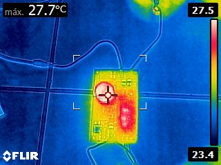
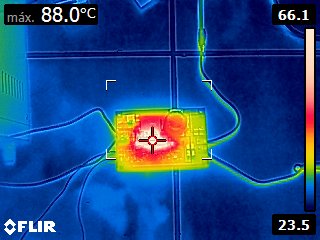
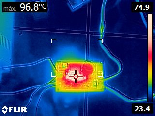
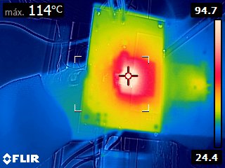
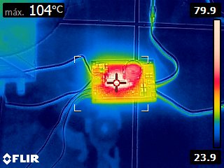
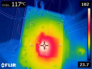
i´ve been working with the lm3429 driver and i have problems with efficiency and heat (heat in the mosfet).

Vin: 12-24 V (12v nominal)

Vout: 46.6V

Iout: 1.2A

How can i get better efficiency? which of mosfet should i use for better heat dissipation(mine is SUD35N10-26P-E3 of vishay)?
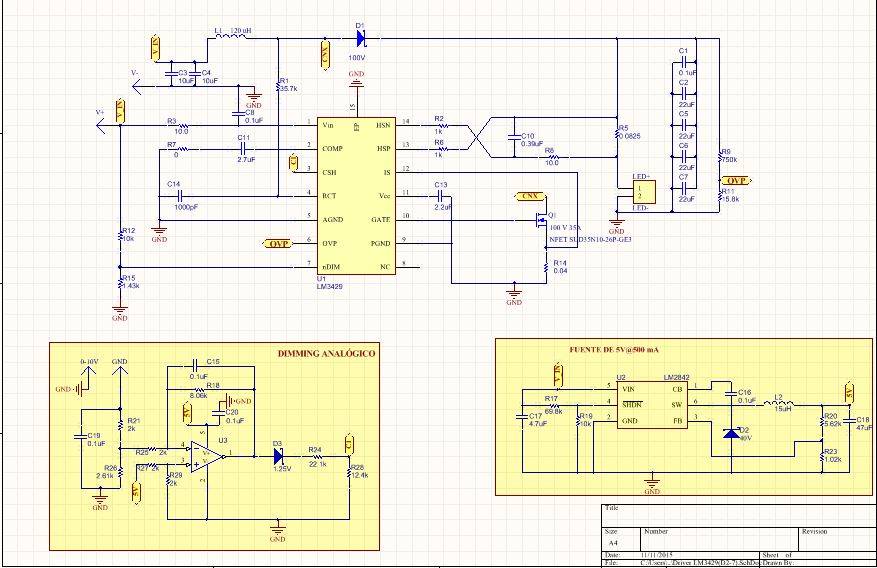
Best regards,

Lauro Castro

SUD35N10-26P-E3

  • Hi Lauro,

    I am checking with our FET team to see if we have a better recommendation for the switching FET. The one you have actually looks pretty good.

    Which inductor are you using? How hot is it getting? Be careful to make sure this does not saturate.


    Regards,
  • The FET you are using has a 47nC gate charge and you are trying to switch at 700kHz. This will require about 33mA from VCC to drive that FET that fast. The VCC current limit of the LM3429 is typically 27mA. So you are current limiting VCC and its voltage is likely dropping as a result. So your FET is not being driven as hard as it should be. That will heat it up a lot due to increased Rds(on), slow switching edges, and the fact that it may not even fully enhance. You need to either get a FET with less than 28nC gate charge (to account for a minimum VCC current limit of 20mA) or you need to lower your switching frequency. This is also why the efficiency is bad. Lowering the switching frequency is always a good way to improve efficiency as well.
  • This is the model of my inductor:

    PM2120-121K-RC - Manufacturer: J.W. Miller

    Inductance: 120uF


    Below, there is a register with the  MOSFET working temperature, :

    t (s) ---- temperature (°C)

    0     ----  26.2°C

    14   ---- 40.0°C

    26  ---- 57°C

    51 ----67°C

    97 ----77°C

    220 ---- 87.6°C

    399 ---- 97°C

    888----104°C

    369 ---- 104°C **

    545 ---- 110°C**

    758--- 113°C**

    900---117°C**

    Notes:

    1) MOSFET is placed on bottom layer.

    2) The measures with asterisk (**) is the region in direct contact with the MOSFET.

    Also, I send some pictures with the thermal camera.

    Thanks for your support John 

  • I changed the switch frequency resistor to 69.8kohms for 358 khz and the mosfet is further heated, I will look for more MOSFETS but if you had one that i could use please let me know the model of MOSFET.

    I appreciate your support thanks Clinton.
  • That's interesting, so VCC current limiting isn't the only factor. Have you looked at the switch node waveforms to make sure there isn't any oscillation or noise related issues and also to verify the switching frequency? Is the output current regulating correctly without any oscillations? That really isn't a bad FET for this application as long as you have a low enough switching frequency. I wondering if there are any layout issues?
  • Here are the waveforms, i think they are ok but if you see something wrong let me know, thanks for the help.

    Switch node (10x attenuation)

    Output LEDs (10x attenuation)

    Gate signal 

    Gate signal zoom

    IS signal ( i change the current limit resistor to 0.025ohms if i did not do it i does not reach the output current of 1.2A )

    if you need the layout could you please give me your email.

    Thank you very much for your support.

  • It seems to be switching ok. Is this possibly just a thermal issue such as not enough heatsinking? You are running pretty high input current (this is a high power application) and you are burning over half a watt in the inductor, almost half a watt in the current limit resistor, and over half a watt in the FET. They are all close together and connected in a small area. It's possible that there just isn't enough copper there for heatsinking purposes. Inadequate heatsinking will manifest itself in that way since as the FET gets hotter its Rds(on) increases so it gets even hotter until you have thermal runaway. You may need to use thicker copper, or a bigger package for the FET and the resistor would help, or in the end if the board needs to be that size (you can't add more copper or inner planes to help heatsink) you may need to use a FET with a heatsink.
  • You still might be able to get away with it if you use a better FET with lower Rds(on). Try the NVD5863NLT4G from On Semi or the Fairchild FDD13AN06A0. Both have lower Rds(on) and lower gate charge than the FET you are using. You will cut down the power dissipation significantly and it might be enough.