This thread has been locked.

If you have a related question, please click the "Ask a related question" button in the top right corner. The newly created question will be automatically linked to this question.

BQ76940

Other Parts Discussed in Thread: BQ76940

Hi,

I have a question. How is the diode function marked by red as below picture?? The diode is between BAT and VC15.

Could I remove this diode??

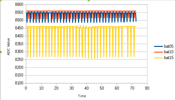
When I detect the 15 cells voltage, the 15th cell voltage is lower than others.

But I removed the diode, the 15th cell voltage will be almost the same with others.


  • The bq76940 will operate without the diode but will likely be damged during connection or severe transients.  See figure 20 of http://www.ti.com/lit/slua749

    If the diode is causing a voltage error there may be something wrong in the circuit.   Normally the load on BAT is small (see the datasheet) and the drop across Rf is much less than a diode drop.  The diode will normally just provide extra capacitance on VC15 except during transients.


  • With these diodes we find the voltage of battery measured at battery 5, 10, and 15 will drop periodially.
    Especially the Bat 15 , it will get lower voltage then measured directly by electric meter. Because there are current pass the dinode to BAT pin of BQ76940.
    If we don't remove these diodes, How to solve the problems ?

  • WM5295 is out of office until Monday for Thanksgiving. Can you wait until then?
  • Are the capacitors between GND, VCx5, VCx10 and VCx15 with correct value? Are these capacitors with short traces to the corresponding pins of bq76940? Also if using improper resistor string to simulate the cells may cause such voltage drops. Can you send us your schematic and layout for further inspection. For one more supplement, if you are testing the EVM with the onboard cell simulating resistor, you need to use separated power to provide power to each group of bq769x0 to obtain ideal performance.

  • The thermistor is biased during the top cell measurement on each group. If the thermistor is shorted, the increased load on the group will be nominally 3.3V/RTS, RTS is shown in the datasheet.  Nominally this will be 0.33 mA, across the recommended typical Rf of 1k 0.33V.  The diode will not conduct if using a conventional diode. If the thermistor is not shorted the current and voltage drop will be smaller. If you are using a resistive cell simulator for test the voltage on that group will drop during the thermistor bias and the top cell of that group will measure a lower voltage.