This thread has been locked.

If you have a related question, please click the "Ask a related question" button in the top right corner. The newly created question will be automatically linked to this question.

LM5064 / VCL(current limit threshold voltage)

Guru 29720 points

Other Parts Discussed in Thread: LM5064

Hi Team,

The datasheet shows VCL is 47~53mV over Tj range of -40~+125℃ when CL=VEE.
My customer saw 45mV of voltage difference between SENSE_K pin and VEE_K pin.

I believe it should fall within 47~53mV but it doesn't.
Is there any concern?

Best Regards,
Yaita / Japan disty

  • Hi Yaita,

    Check out this blog regarding sense resistor layout:
    e2e.ti.com/.../choosing-the-right-sense-resistor-layout

    Are they using one of these layout schemes?

    And did they measure SENSE_K and VEE_K pins at the IC itself, or did they measure it at the sense resistor? Measuring at the sense resistor can cause issues due to solder resistance, or sense resistor inaccuracy. The best technique would be soldering two small wires on the LM5064 IC pins itself and read with an external multimeter.

    Thanks!
    Alex
  • Alex-san,

    I will reply instead of Yaita.
    Our customer measured the voltage between SENSE and VEE pin again because LM5064 detects current limit by SENSE and VEE voltage.
    Then the voltage difference was 46.4mV. It was a little lower than datasheet characteristic.

    Do you have any idea for this cause?

    Best Regards,
    Kohei Sasaki

  • Hi Kohei,

    One reason it can trip SLIGHTLY early is a little bit complicated:

    The TIMER pin starts the charging the timer capacitor SLIGHTLY before the current limit regulation loop controls the GATE voltage. This is done on purpose, in order to ensure that if the device is ever in a current limit or power limit regulation loop, the TIMER is definitely running.

    If the device did not have this feature, then it would be possible for the device to be in a power limit/current limit and the TIMER would not be running. This would risk the MOSFET failing, due to the absense of a timeout.

    Since the device does have this feature, it means that if you very gradually increase the current, in order to find the "current limit" trip point, you will actually measure the point at which the TIMER begins charging, expires, and shuts off the GATE. If you capture a waveform, you will see the GATE remain fully enhanced the entire time (does not decrease gradually, in order to regulate), and then shuts off once the TIMER expires.

    If you increase the current a bit quicker, you will see the GATE voltage reduce and regulate the current. Then the GATE will eventually shut off once the TIMER expires.


    So this would be one factor of why you may see it trip "slightly early". From my bench testing, I typically see it cause about a 1mV difference. If this was tested at extreme temperatures (-40C or 125C) and you saw a 46.4mV trip, I would not be too surprised. But if this was tested at room temperature (which I am guessing it was), then 46.4mV would be lower than I would expect. If they truly measured this trip voltage at the IC pins itself, then I can only guess that the LM5064 IC could potentially be damaged.


    Every piece of silicon is tested, prior to being shipped, to ensure it operates well within the EC table characteristics. If available, I would recommend contacting a local TI office to see if a failure analysis can be performed on this IC.

    Have they tried replacing the device to see if others behave the same, or trip at a higher voltage?

    One final possibility could be if the device is poorly soldered on, and solder resistance on the VEE pin is large enough such that the current through the IC is producing a couple mV of voltage drop.

    Thanks!
    Alex
  • Alex-san,

    Could you send me the VCL measurement test data if you have?
    Please send to the following e-mail address directly if it is the data that you can't open.

    sasaki-k@clv.macnica.co.jp

    Best Regards,
    Kohei Sasaki

  • Hi Kohei,

    I do not have this data recorded for the LM5064 specifically. I will run some tests in the lab to show you the difference.

    Will provide the test results this week (by tomorrow).

    Thanks!
    Alex
  • Alex-san,

    Thank you for your support.
    I'm looking forward to receiving your test result.

    Best Regards,
    Kohei Sasaki
  • Hi Kohei,

    I just finished up some testing in our lab. I will need further time to analyze the behavior and discuss with our team.

    NOTE: All waveforms are taken with respect to Vee as the oscilloscope probe ground.

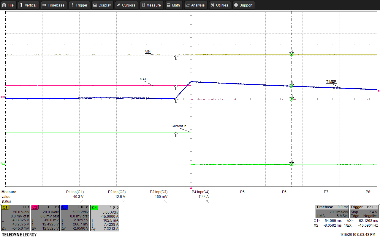
    First waveform is using a constant current electronic load, gradually raising the current. When performing this test, you will see the TIMER pin begin to charge, while the GATE does not move. This is because the TIMER pin will begin to charge, just below the current limit regulation point. This is made to ensure the TIMER is always running whenever the circuit is in regulation.

    So the TIMER begins to run around 7.4A, which is much less than the 8.67A current limit set point of the EVM (based on 3mohm sense resistor). I will need to investigate this further, probably by checking the Vsns voltage across the sense resistor.

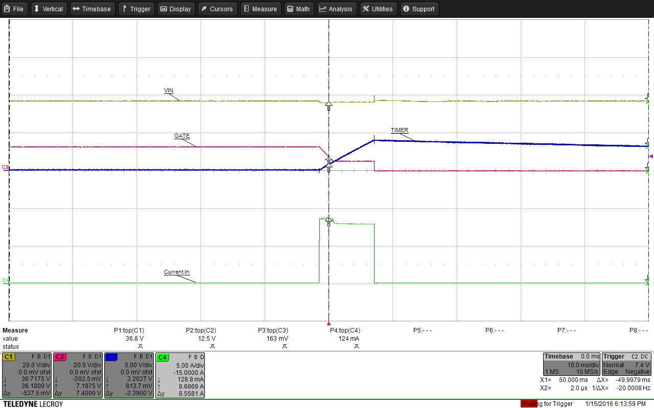
    The next test was a load step using a constant current electronic load.

    Here the gate voltage is reduced and the circuit is in regulation. Here the current is a little higher, at 7.82A.

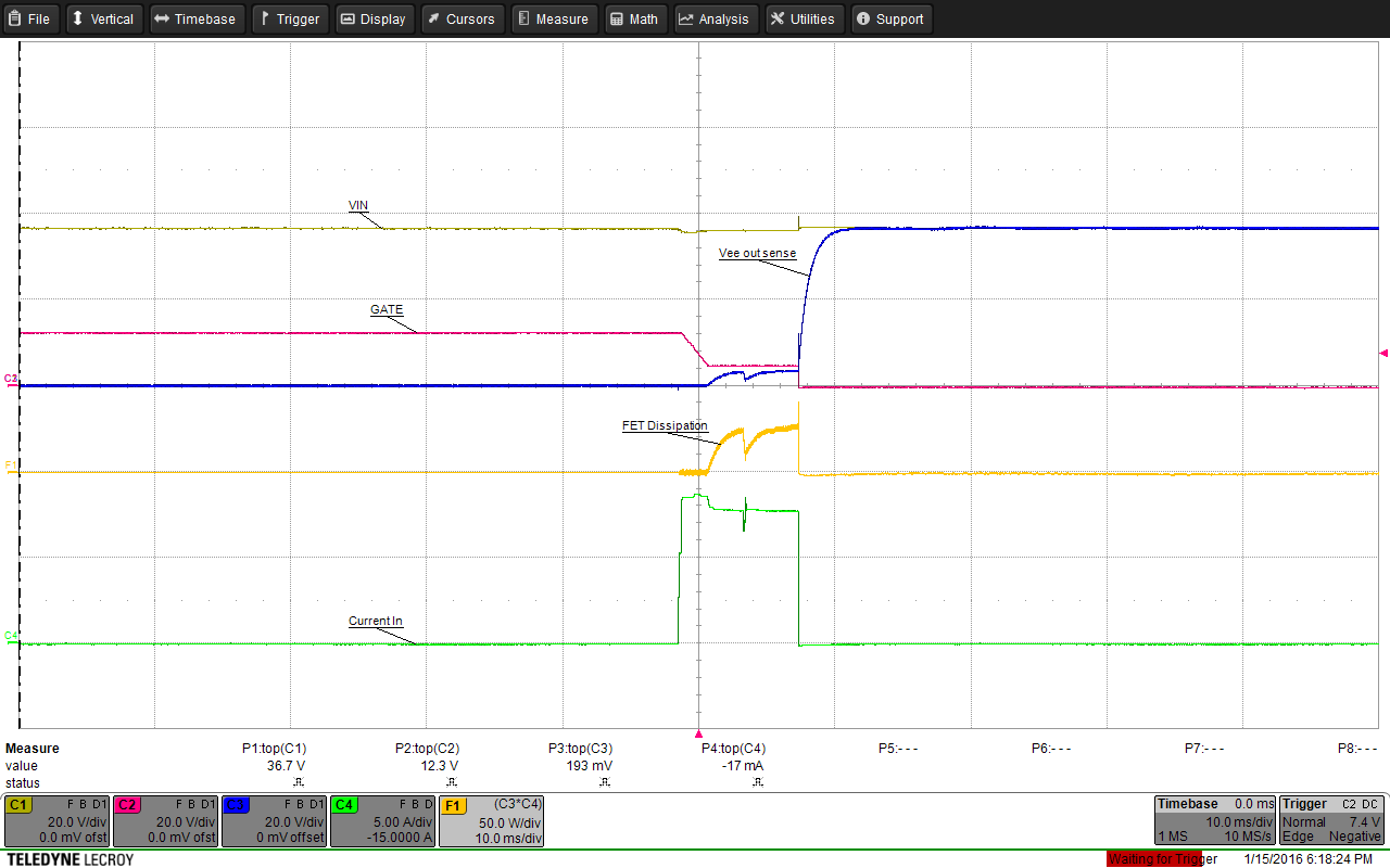
    For the last test, I used a resistive load and hot-plugged.

    Here we can see that the device began limiting the current to 8.69A (which is right at the current limit set point!) but this was for a brief duration of time. Quickly, the circuit reduced the current and continued to regulate.

    I performed the same test but captured Vee_out_sense in order to check what the MOSFET power dissipation looked like.

    Here we can see the MOSFET power dissipation is around 25W, which is well below the power limit. So it may not be in power limit regulation, but yet the current limit was reduced. Will need to analyze further.

    So overall we are able to replicate some inaccuracy in the theoretical set point threshold and the measurement on the bench. We will need to check what is the root cause.

    Note I am out of office on Monday 1/18 and will return on Tuesday 1/19. I will begin to dig further next week and will keep you posted on the results.

    Thanks!

    Alex

  • Alex-san,

    Thank you for your test result. I'm looking forward to getting your update.

    Your first test method is the same as our customer.  And test result is the same, too, they also observed that VCL was lower than the datasheet characteristic value.

    Best Regards,
    Kohei Sasaki

  • Hi Kohei,

    I understand and discussed with our team of system, applications, and design engineers.

    We will modify the EVM tested above in order to very accurately measure its regulation point and check if it is outside the EC table spec. We are hoping to get the test results this week.

    Thanks!
    Alex
  • Hi Kohei,

    As mentioned, we were hoping to get the results this week but unfortunately could not.

    We have a modified EVM built up and plan to begin testing on Monday. I will keep you updated from Monday onwards, every 2x days, until the root cause is determined.

    This is an important test for us, since we were already able to replicate the issue on a default EVM. We would like a speedy resolution.

    Thanks,
    Alex
  • Hi Kohei,

    So I modified an EVM with the following changes in order to very accurately measure the point at which the TIMER begins to charge and where the current limit regulation point is:

    1. Changed Rsns from 3mohm to 1ohm.
    2. Added Cgs capacitance of 100nF to prevent GATE oscillations due to small current limit set point.
    3. Soldered wires to pins 8 and 9 (Vsns points) directly on LM5064 IC pins themselves for best measurement.
    4. Removed output capacitors.
    5. Added external resistive load (mechanical) which can be varied from 1ohm up to 1Mohm in just 1ohm increments.

    After VIN power applied (to get past insertion time):
    6. Added a 10k resistor from TIMER to VEE. This prevents the TIMER from timing out during testing, but allows you to see when the TIMER pin has sourcing current.

    After these modifications, the current is slowly increased (dialed resistive load in) up until the point where TIMER reads roughly 0.9V. This is the point at which the TIMER begins sourcing current, but the GATE voltage is not reduced (the device is not in current limit regulation.

    This point was measured to be 23.5mV.

    Then, the current is still slowly increased until the point at which the GATE voltage is reduced. This is the point where the circuit reaches regulation.

    This voltage threshold was measured to be 24.8mV.

    This experiment was repeated with the same IC several times, but the measurements were always the same. For this IC, the TIMER began running at precisely 23.5mV and the current limit threshold is precisely 24.8mV

    So the IC is operating within spec (though only room temperature testing was conducted). The point at which the TIMER begins to charge is not spec'd, but in this case it was 1.3mV below the current limit threshold.

    So at this point, the issue the customer is seeing may be due to sense resistor accuracy / layout.

    Please note that 2512 resistors can be inaccurate, even if they are purchased as 1% tolerance. I will switch the resistor back to the default EVM and try to measure the Vsns current limit threshold again. My guess is that the layout is the root cause of the descrepency. They can check out this blog for more details on current sensing for hot swap design. Using a 4-pad sensing technique tends to give more optimal results:
    e2e.ti.com/.../choosing-the-right-sense-resistor-layout

    For reference, this experiment was repeated with CL = VEE. The timer began charging at 46.3mV and the current limit regulation point was at 47.9mV.

    Thanks!
    Alex
  • Alex-san,

    Thank you for your update.
    I understood that LM5064 TIMER pin begins sourcing current at a little lower point of VCL threshold. According to your test result, it was about 1.5mV, however this is not defined in datasheet.
    So VCL threshold had been looked lower than datasheet spec when load current is gradually increased.

    I will tell our customer about this.
    Please let me ask you if I have additional question.

    Best Regards,
    Kohei Sasaki

  • Alex-san,

    How much is the voltage range that  LM5064 TIMER pin begins sourcing current at a little lower point of VCL threshold.
    We would like to know how much lower from VCL threshold because our customer has to chaneg their current limit value depend on the variation.
    Could you provide the value such as min **mV to max **mV?

    Best Regards,
    Kohei Sasaki

  • Hi Kohei-san,

    The threshold of Vsns at which the TIMER begins sourcing current has not been characterized and is not a spec in the EC table in the datasheet.

    As a result, we unfortunately cannot provide min to max mV value.

    Based on the last test result, we recommend they assume a worst-case value of 1.5mV x 2 for design margin over temperature. This is an estimate based on measured value and potential variance.

    Thanks!

    Alex