This thread has been locked.

If you have a related question, please click the "Ask a related question" button in the top right corner. The newly created question will be automatically linked to this question.

Inductor, Output Capacitor Selection- Mismatch in Calculation and Webench design value for TPS61032

Other Parts Discussed in Thread: TPS61032, TPS61070

Hello,

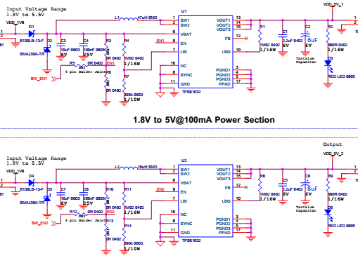
I need help regarding selection of Inductor and Capacitor values for 1.8V to 5V@100mA and 250mA output.

I calculated Inductor value as per datasheet and for 1.8V to 5V@100mA it is approx. 55uH and for 1.8V to 5V@250mA it is approx. 22uH but as per webench data Inductor Value for 1.8V to 5V@100mA it is approx. 22uH and for 1.8V to 5V@250mA it is approx. 8uH. 

please help me for choosing this values

Thanks in advance

  • for 250mA output, the input current is approx. 0.87A, the inductor should be 1.8*3.2/(0.2*0.87*0.65*5)=10uH.
    for this 100mA output current, you don't need to follow equation in the datasheet to select the inductor value. because the inductor value will be too high and hard to find in the market. you can still used a 10uH inductor.
  • Hello,

    Thanks for the Answer..
    But I can not understand that input current is 0.87A It may be IL(based on equation). In equation it is ripple inductor current

    In datasheet it is given like: "10% × IL" and as per datasheet: IL= (Iout*Vout)/(Vbat*0.8) and as per calculation IL= 22.1uH and In replied it is taken 20% x IL so I am still confuse for choosing this value

    Inductor Selection Calculation:

    L=(VBAT*(VOUT-VBAT))/(IRIPPLE*fSW*VOUT)

    Where,

    VBAT(V)-1.8V

    VOUT(V)- 5V

    fSW(kHz)- 600KHz

    IRIPPLE(mA)- deltaIL= 10% of IL

    And For Output Capacitor Selection for 1.8V to 5V@100mA:

    Cmin.- 5.33uF (as per datasheet calculation) for that deltaV i have used 20mV(10mV+10mV) , RESR i have used 100mohm

    and for 1.8V to 5V@250mA:

    Cmin.- 7.619uF (as per datasheet calculation) for that deltaV i have used 35mV(25mV+10mV) , RESR i have used 100mohm

     Cout 47uF value which is different in webench simulation so please help for it.

  • in the small current application, the inductor current ripple should increase , or it would result in very large value inductor.

    for the output capacitor, it is selected based on the voltage ripple and stability. a 47uF capacitor should be used for the stable operation of this device. and in series with 30mohm resistor if ceramic capacitor is used.

    you can share the schematic when it is ready. so i can help to check.

  •  Kindly find my circuit and is it correct?

  • Hello Second circuit is for 5V@250mA output
  • 1. the 47uH is too large. during the startup of this device, the input current is 0.4*Isw=1.6A, I guess it is not easy to find such a inductor. and large inductor may cause stability problem. you can use 10uH inductor for both application.
    2. the output capacitor is too small. please used a 47uF tan cap.

    another device that can support 5V&100mA is the TPS61070, this device is simpler than TPS61032.
  • Hello Jasper Li,


    Thank you for the Answer but calculation is most of the time differ from simulation so sometimes it is confusing to choose the values so which is the correct method to design with understanding of design.

    Thank you again for your all this answers...

  • there are several factor that impact the selection of the inductor and capacitor for a boost converter: current ripple/ voltage ripple, stability (because the boost converter is optimized to operation at some range of inductor and capacitor), current rate/voltage rate, and also the price of the component.

    the inductor current ripple is not a very important factor in a boost converter IC. for example, if the IOUT=10mA, it doesn't mean a hundreds uH inductor should be selected.

    Actually the easiest way to start is to follow the EVM, the EVM can support no load to full load condition.
  • Thank you for  All this Answers...


    Thank You!