This thread has been locked.

If you have a related question, please click the "Ask a related question" button in the top right corner. The newly created question will be automatically linked to this question.

LM3429 - N Channel MOSFET Heating

Other Parts Discussed in Thread: LM3429, CSD18534Q5A

Hello TI,

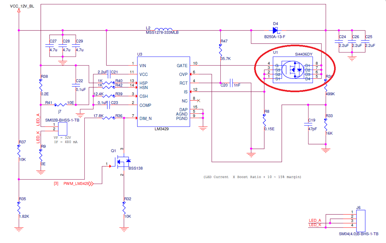
I have designed LED driver board using LM3429 IC. The LCD back light specification is 32V @ 480 mA. When I power on the LCD driver board, the N-channel MOSFET (U1) associated connected with LM3429 (pin number 10 & 12) getting heating. Please let us know the reason for the heating ?

Regards,
Azlum

  • It's hard to say without more information but it could just be not enough heatsinking, it could be other power dissipating components all close together, or it could be the package isn't adequate. The Rds(on) of the FET you chose is low which is good, but a rough estimate is that at 700kHz switching frequency you will be burning almost half a watt just due to AC losses in that FET. If you need to switch that fast you may need to use a package with better thermal characteristics such as a dpak or something with a DAP to solder to the board.
  • Dear Clinton Jensen,

    OK. I will check other components power dissipation. 

    I design the OVP for 39V. But when I power-on the board without load (not connecting back light), the anode and cathode terminal of board shows 34V. 

    I guess voltage between anode & cathode without any load suppose to be 39V, not 34V. I'm correct ?

    Regards,

    Azlum

  • Are you looking at the output voltage waveform or just measuring it with a multimeter? Yes, your OVP setting is around 39V. But you have set a hysteresis (with the upper resistor, see datasheet for more info) of about 10V. So the LM3429 will stop switching when Vout reaches 39V and the output will discharge to about 29V before it starts switching and repeats the process. So you are likely reading the average output voltage, but if you look at the waveform it will look something like a triangle wave with an average around 36V.
  • Dear Clinton Jensen,

    I have checked through miltimeter and measured 34V output across anode and cathode terminal. My LCD support max 32V @ 480mA for back light. But I designed OVP for 39V and this 39V OVP will damage the LCD ?

    Could you confirm ?

    Regards,
    Azlum
  • HI Azlum,

    Have you looked at the gate of the FET during operation? I am wondering if it is floating up as the voltage at the drain is rising.

    We have the CSD18534Q5A which has a lower gate charge and may be easier to control.

    It would be great if you could share some waveforms.

    Regards,

  • Dear John Cummings,

    I have mounted Si4435DY (P-Channel) instead of Si4436DY (N-channel). This was causing problem of heating MOSFET. I have changed P-channel to N-channel. Its working fine without any problems.

    Regarding GATE voltage, it is pulsating. I guess pulsating gate voltage is proper.

    Below I have one more question:-
    My LCD support max 32V @ 480mA for back light. Since OVP is 39V and VHYS is 10V, the avarege output will come 34 (2 volate is extra than my required voltage). This will damage the LCD ?


    Regards,
    Azlum
  • Is this voltage connected to the LCD in any way. It should just be connected to the LEDs, unless the output is open. But that shouldn't damage anything that isn't directly connected to the output. If something else is for some reason you would need to consult the LCD specs.

  • Dear Clinton Jensen,

    The anode and cathode will be connected to the LCD's back light terminal.

    Regards,
    Azlum
  • Dear Clinton Jensen,

    I have found one more observation in board. The switching sound (Tik..Tik) is coming he from the inductor L2. Could you please tell me what could be the reason ?

    Regards,
    Azlum
  • Is this sound happening during normal operation or with an open output?

    As for the LCD, you should only be connected to the LEDs. If there is an open circuit of the LEDs the 39V should not be touching anything else in there. Of course if your LED string opens the LCD might be considered a failure in any case.

  • Dear Clinton Jensen,

    When I connected the LCD, the sound has been isolated. Now I have below observation:-

    When I connect the TI LED driver board (LM3429) with LCD (32V, 480mA), the back light is glowing. But the data is not displaying properly.
    When I change the LED driver board (XL6006 IC), LCD back light is glowing and image also can be visible.

    What could be the problem with LED driver ?
  • If the LEDs are lighting properly then it is probably a system issue. Maybe interference of some sort? The XL6006 switches at 180kHz which maybe doesn't bother anything in your system. Have you tried changing the switching frequency of the LM3429 to see if that has any effect?

  • Dear Clinton Jensen,

    I have changed the RT value. But still the effect is same.

    Could you look into the schematic. I have mounted 30V N-MOSFET (U1) , because 60V N-channel MOSFET was not available when I assembled the board. This can cause any problem ?

    Regards,
    Azlum
  • Yes. You are overvoltaging your FET and it is avalanching each cycle. It's amazing it hasn't failed completely yet. That would also generate a ton of EMI.