This thread has been locked.

If you have a related question, please click the "Ask a related question" button in the top right corner. The newly created question will be automatically linked to this question.

BQ27510-G3 Nominal AVailable Capacity

Other Parts Discussed in Thread: BQ27510-G3, EV2400, BQSTUDIO, BQ27510

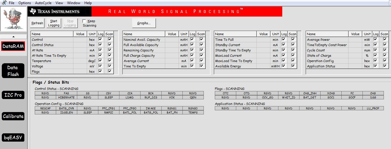
For BQ27510-G3, how can i update the nominal available capacity [ NominalAvailableCapacity() NAC ]. How can I update this parameter, so that I can get the correct full available capacity, remaining capacity and full charge capacity.

From the technical manual, it is written as a Read Command only.

Please advice

  • Hi Wang,

    If the purpose is to get a correct full available capacity, what should be done is to update the parameter "Design Capacity" to correspond with your battery's capacity and then run a learning cycle. (Please note that there are other values that should be updated in addition to Design Capacity, and should correspond to the battery you are using and the application it is used in.) As you do a learning cycle, the gauge will learn a more accurate value for this.

    Please refer to this app note on achieving a successful learning cycle to learn more.

    Best,

    Justin

  • Hi Justin,

    Thanks for the feedback. Appreciate it.

    In this case, if I want to Mass Production my product with BQ27510-G3, do i need to do the learning cycle for each IC??
    The total run rate is 8k. Our side can't afford to do this learning cycle one by one.

    The default capacity is 1000mAh. But my battery is 100mAh.
    I already done the Design Capacity write to 1800mAh. But when shut down, the capacity return to 1000mAh.
    Thus, i need to the learning cycle.

    Is there any better option for this problem for Mass Production?

    Thanks,
    BR,
    Jason
  • Hi Jason,

    You just need to achieve a successful learning cycle once and then extract a golden file. When you go to mass production, you will flash your devices with that golden image.

    If the battery's capacity is 100mAh, this is what you will set the Design Capacity to before running the learning cycle. Your actual maximum capacity will be adjusted to a more accurate value after you complete the cycle successfully.

    Best,
    Justin
  • Hi Justin,

    Thanks for the info!

    So, to extract the golden file, do i need the TI's BQ Evaluation software or any 3rd party software? 

    In order to run the learning cycle, it needed I2C communication and TI's BQ Evaluation software.

    Currently our side is using the UART communication and 3rd party software platform to program the BQ27510-G3 instead of the BQ Evaluation software.

    Thanks,

    BR,

    Jason

  • Hi Jason,

    Yes, you would use bqStudio with the device connected via the I2C communication of an EV2400 or EV2300 to create the golden file. Afterward you can use this golden file to flash your production devices.

    When the learning cycle is successful, you will go to the Golden Image tab of bqStudio, and here you can generate the files used for production.

    Best,
    Justin
  • Hi Justin,

    Thanks for the info!! Appreciate it! :-)

    Beside using this bqstudio and I2C communication for this flashing and golden file extraction purpose, is there any other method to do so?

    Currently our side the PCB (printed circuit board) already been fabricated out. But we didn't provide the external I2C connection to interface with the EV2400.
    Previously we didn't know it needed to run this learning cycle.

    But in our circuit, we do have I2C communication with the MCU for BQ27510-G3.
    Can we do the flashing and learning cycle (golden image) through MCU. We do have MCU external debugger connection.

    TI FAE do suggest us to externally flash the golden image to the BQ27510-G3 first before running auto mounting process during Mass Production.
    May i ask is there any IDE available at TI for us to place the BQ27510 for programming using EV2400.
    (like an external socket placement for BQ27510-G3 flashing purpose??)

    Thanks,
    BR,
    Jason
  • Hi Jason,

    It's okay if you only have I2C communication to the gauge via your host, you will still be able to write to the gauge. After completing you learning cycle, you can generate a DFFS file (in the golden image tab of bqStudio) . This will have all the parameters that make up the data flash. Your host will parse the data and use this to send blocks to the gauge.

    In section 1.1 of this app note, you will see the meaning of each of the letters (W,R,C,X). You can use this DFFS file to program your gauge.

    Best,

    Justin

  • Hi Justin,

    For the BQstudio, can you please send the the instruction on how to perform the learning cycle?

    I cant find any interface at the bqstudio that is used to perform the learning cycle.

    Thanks,

    BR,

    Jason

  • Hi Wang,

    bqStudio does not use a built in tool to perform the learning cycle. You can run a learning cycle by following the guidelines in the app note I posted in the first post of this thread.

    If you have a GDK, you can use the GDK tab in bqStudio to set up an automated charge and discharge schedule that matches the guidelines in the appnote.

    If you are not using a GDK, you can use a source meter instead for the charge and discharge.

    Best,
    Justin