This thread has been locked.

If you have a related question, please click the "Ask a related question" button in the top right corner. The newly created question will be automatically linked to this question.

Broken TPS62130 ?

Other Parts Discussed in Thread: TPS62130

Hi All,

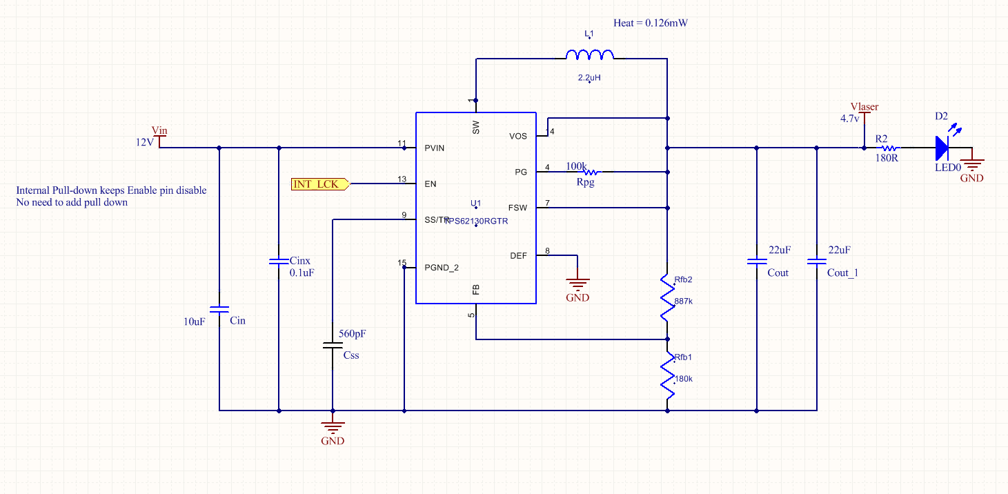
I have a problem with the TPS62130. When I plug it in, the TPS62130 either breaks or gets 10.1V on Vout (3.1V on FB pin).

I have another board working perfectly with the same components. Do you have an idea?

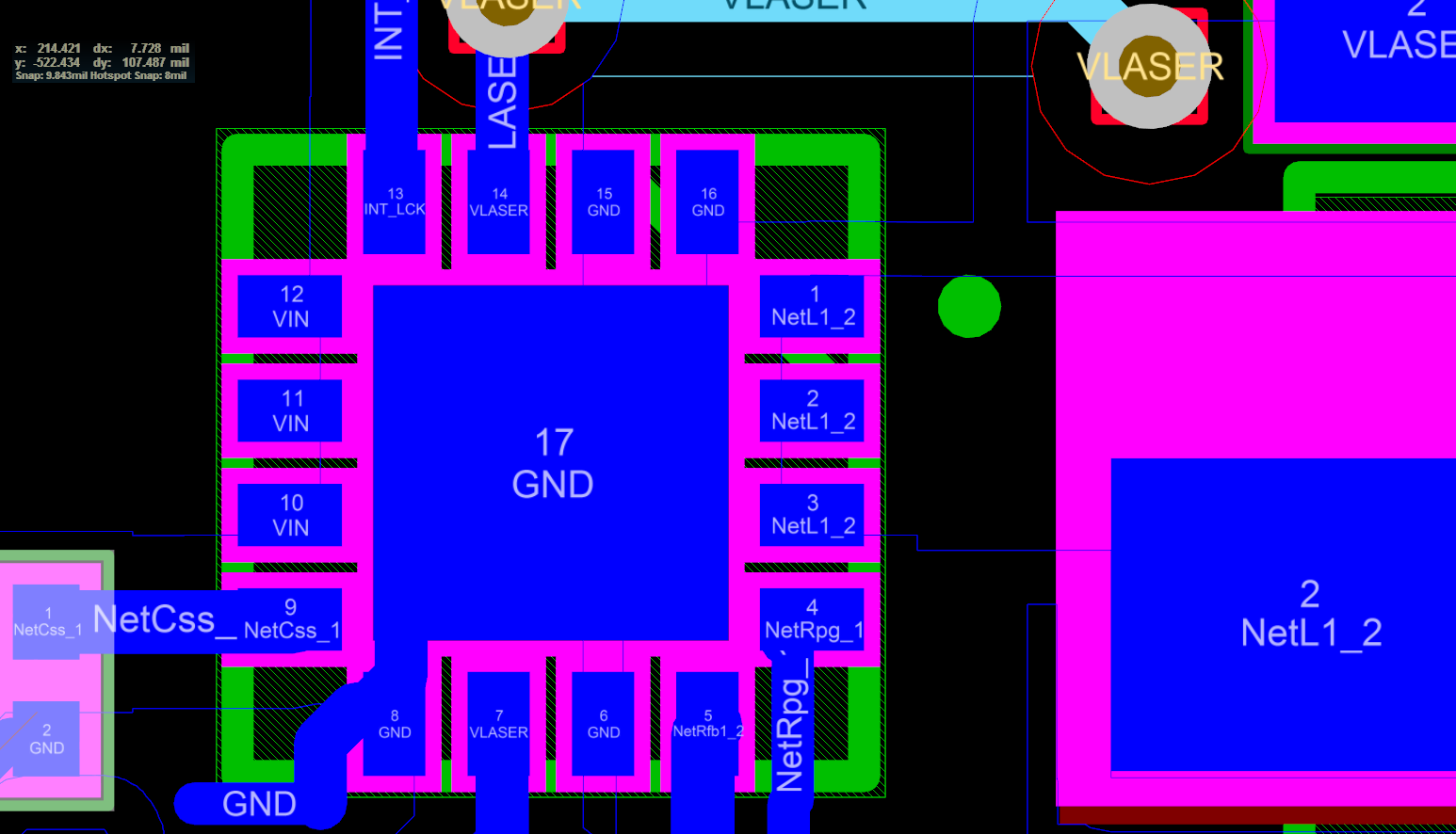
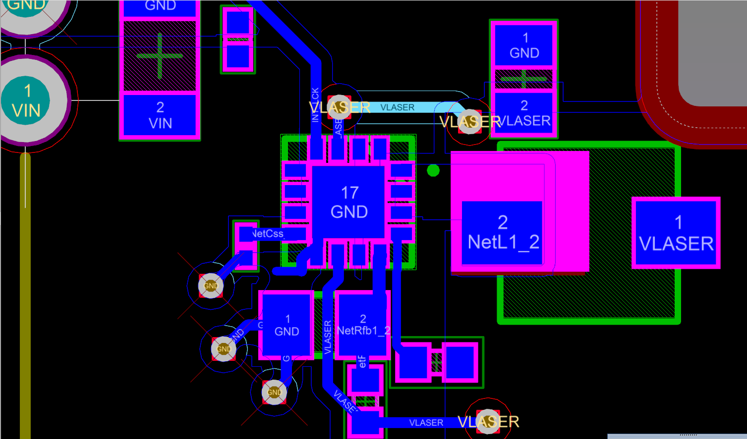
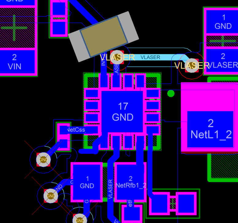
Here are the schematics and board layouts.

1) The ouput current is only the LED right now.. so around 30mA.

  • Hi Paul,

    thanks for sharing the schematic and layout.

    What do you mean by plug it in? Is this like hot plugging?

    Why do you use a schematic symbol with only 10 pins? Is it for simplicity?

    Regarding the layout:
    I cannot see how the GND of your input capacitor is connected to the Device GND.
    I highly recommend to follow the layout guidelines in the DS page 27 and place the input cap close to the TPS62130 device with a direct connection of the GND.
    You should also connect the RFB1 and the Css to the AGND pin of the TPS62130 as recommended.


    Thanks & Regards,
    Michael
  • What do you mean by plug it in? Is this like hot plugging? No.. I mean when I power it up, when I apply 12v on the input.

    Why do you use a schematic symbol with only 10 pins? Is it for simplicity? I exported it from webench.. Some symbols are on top of each others (the similar pins).

    I cannot see how the GND of your input capacitor is connected to the Device GND. I agree that the GND layout, it is the weak link of this board. We tried adding a large and short wire from the GND of the input capacitor to the GND of the output capacitor and it doesn't change anything. 

    You should also connect the RFB1 and the Css to the AGND : they are connected via a GND plane.

    I agree that the problem in this case may be the layout, but is there any way we can make this board work as it is?

  • Hi,

    So you can exclude a over-voltage on the TPS62130 input when plug in?

    I saw that the RFB1 and Css are connected via a GND plane. To get best accuracy they have to be connected directly to AGND as recommended in the DS.

    Is this just a test board? You could also order the TPS62130EVM with a good known layout.

    Adding a wire is still not good. You could try to cut the solder-mask and place the input capacitor close to the device and see if this helps.

    But clearly you have to change the layout.

    Regards