We have been building a product that uses the UCC28700 for several years now. We have thousands of them in the field and have not had any production problems. The only issue when we first started was that the power supply would sometimes shut down and then start back up when a solenoid on the board was activated. This problem was solved by adding a 10pF cap to the VS pin.
Now we are getting a new board ready for production and are having problems with the power supply. Of the 12 boards built, 5 work fine, 2 put out greater than the designed 5V and 5 do not start up at all.
Aside from swapping a few layers we have not made any layout changes. Basically the aux winding signal went from being sandwiched between earth ground and signal ground layers to just have signal ground underneath it. Similarly the FET ccontrol signals went from having just signal ground underneath to being sandwiched between signal ground and earth ground. (I do not know why the layers were swapped. Not my decision!)
Of the 5 boards that work, 2 have been used for software development for several months without any problem.
On the two boards that put out more than 5V, one puts out 6V and the other 8V. If I remove the 10pF cap on VS they both put out 5V. In the past I noticed increasing the cap on VS caused the voltage to rise but not nearly this much.
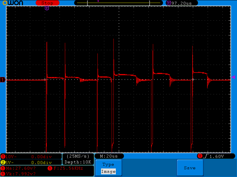
The boards that do not start up all put out the three pulses on the FET driver, then three more and then stops for a bit before trying again. When the first board we tested did not start up we ended up replacing the transformer, UCC28700, FET and current sense resistor. When we replaced the last three items (probe slip blew them up) the board worked and was used for testing for a few days. Then another probe slip blew up it up again and after replacing the parts it did not start up again.
We have been through all the kit parts making sure they are correct. I've tried increasing and decreasing the load (very low on startup). I've played around with the cap values on VS and the snubber circuit. The circuit boards themselves are from two different runs so it seems unlikely it is a board defect.
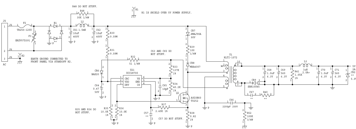
At this point I'm looking for suggestions. I've attached a schematic and capture of the aux winding on a board that does not start up.
Thanks