This thread has been locked.

If you have a related question, please click the "Ask a related question" button in the top right corner. The newly created question will be automatically linked to this question.

BQ24620 high FET not turning on

Other Parts Discussed in Thread: BQ24620

Hi

I would appreciate any ideas about this....


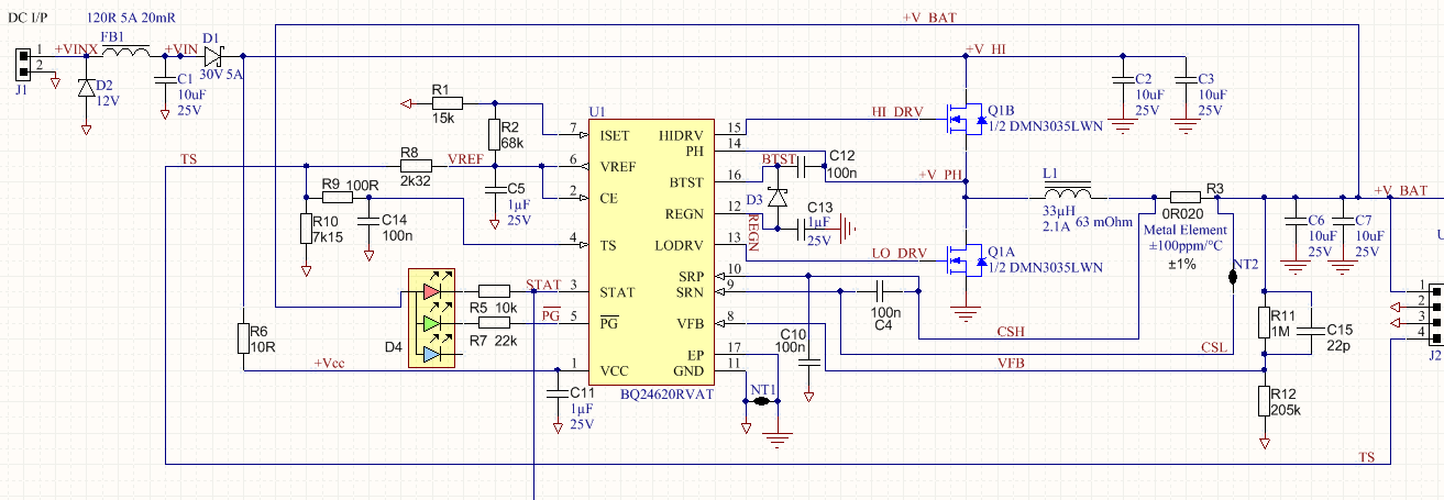
My prototype BQ24620 charger circuit does not turn on the high switching FET. The status outputs indicate a normal "charging" state (no flashing error indication).

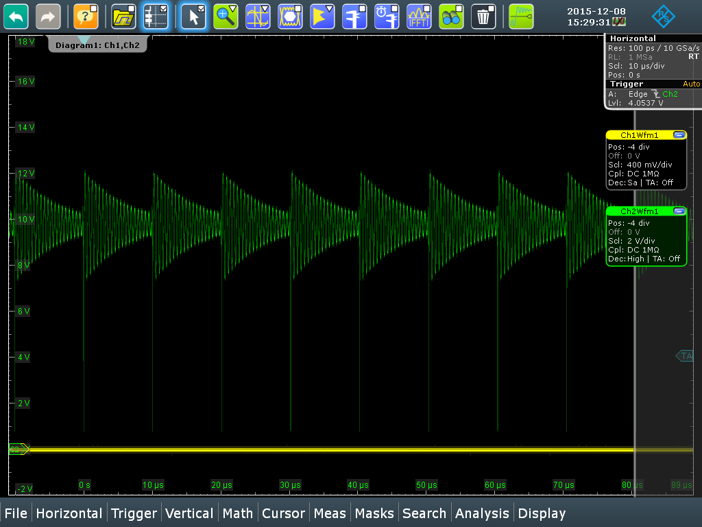
See below circuit, and scope shot of the switching node. You can see the bottom FET turning on but not the top one. The battery voltage is 10V and the supply about 13V. The thermistor, current sense and feedback inputs seem to be in range as far as I can see. The HI_DRV gate is an exact copy of the switching node (but they are not shorted). So there is no net drive to the FET. The switching node just floats at the battery voltage then gets pulled low by the low FET.

Thanks

John

  • John,

    A few questions:

    1. What is the voltage on the REGN pin? If the high side FET isn't turning on (but the waveform on HIDRV looks just like SW), then REGN may not be providing the gate drive needed to turn on the FET.
    2. What is the voltage on VCC and SRN? Your power supply may be at 13V, but after the inductor, diode, and resistor drop, the voltage is much lower than 13V at the VCC pin. (VCC-SRN) needs to be great than 500mV to stay out of sleep mode.
    3. Could you provide a scope capture showing the HIDRV and LODRV pin switching on a single capture? Please zoom in to show 2-3 switching cycles.

  • Hi,

    Sorry for the delay - I had to rebuild my test PCB due to letting out the magic smoke...

    Voltages are:

    • REGN: 6V
    • VCC: 15V (I increased it just in case but it was 11.7V before)
    • SRN: 9.602

    Some others:

    • VREF: 3.307
    • VFB: 1.645
    • ISET: 0.596
    • SRP: 9.602
    • TS: 2.172
    • /PG: LOW = ON
    • STAT: LOW = "CHARGING"

    Here are the scope shots, I guess it is just pulsing the LO_DRV occasionally to operate the charge pump.

    CH2 = LO_DRV

    CH1 = HI_DRV

    CH3 = PH / SW

    A closeup

    Thanks

    John

  • For the benefit of future googlers, this problem is now fixed.

    Basically the chip was failing due to incorrect wiring of the external FET.