This thread has been locked.

If you have a related question, please click the "Ask a related question" button in the top right corner. The newly created question will be automatically linked to this question.

TPS65150 Not functioning after some power cycles

Other Parts Discussed in Thread: TPS65150

Hi,

I am using TPS65150 for LCD bias application.
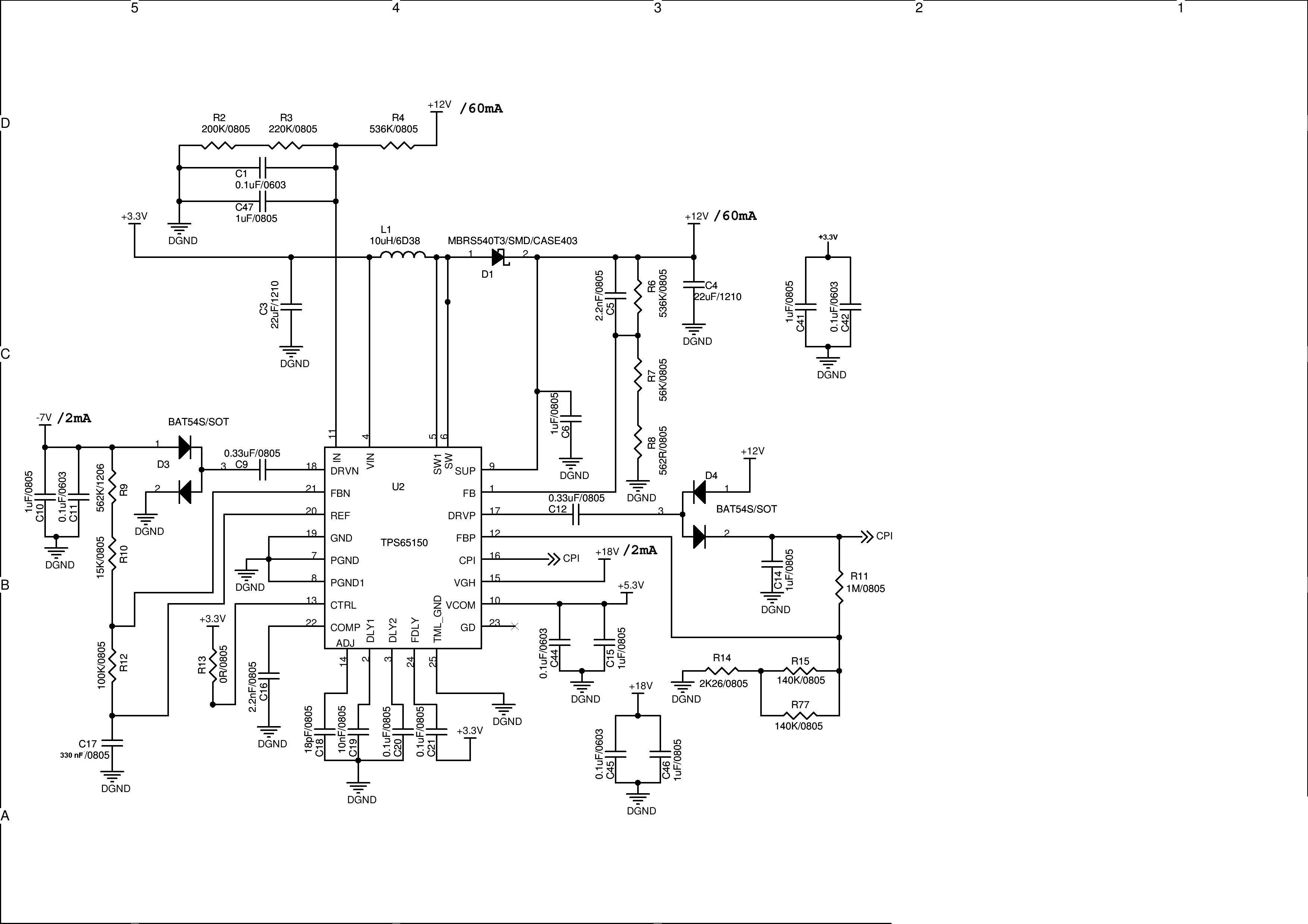
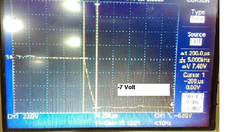
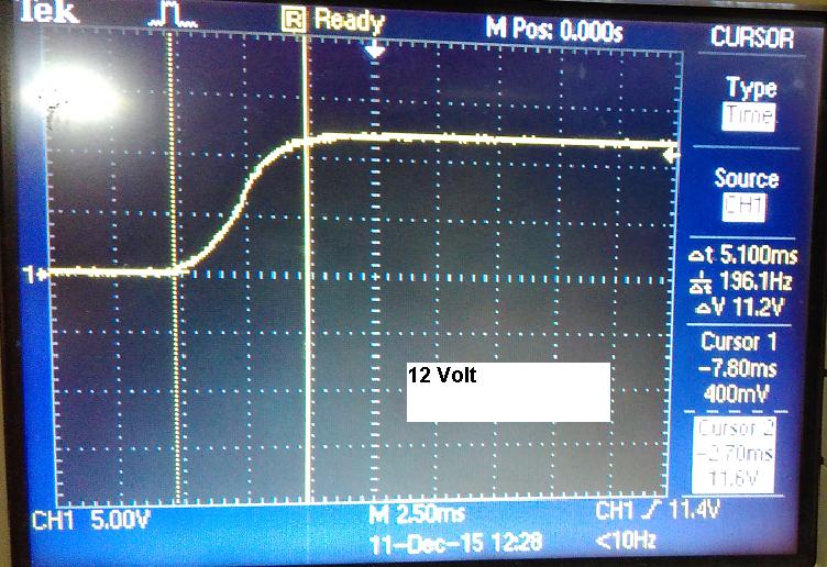
We have seen some issue related to IC that is, The IC will not be functional after some power cycles,(All the out put voltages will be zero including both buck and boost section of the IC ) and it is requires a power cycles to become functional again. The schematic section of the circuit related to this IC is attaching here with actual value of components.
Requesting you to review the circuit and share your feed back for this issue.


Thanks in advance,
Basith

  • Hello Basith,

    Can you do some scope-plots showing the behavior? I am especially interested in the load behavior as well as the input voltage. What you should also look at is the FDLY- signal.

    Thank you,
    Ilona
  • Hello Basith,

    Is this problem still topical?

    Thank you,
    Regards,
    ilona
  • Hi Ilona,


    Extremely sorry for late reply..

    I have captured the rise time for 3 voltage levels  VS,VGH,VGL in actual power sequence. Not able capture the waveform in problematic condition. 

    I feel there is a relation between fault mode and this issue, I am not able not reproduce the issue if I short the fault delay capacitor(Disabling fault mode) and issue is reproducible if I put back capacitor. I have conformed that All loads are with in range of VS,VGH,VGL current limits.

    Please give your suggestions ..

    Inserting the waveforms captured (In normal condition)

  • Hello Basith,

    I assume you are using the non-Q1 version, is that correct? Can you describe the failing condition in more detail:
    How long does the boost-converter switch before it turns off? Some us or ms? How does the voltage look like at FDLY- pin?

    Thank you,
    Regards,
    Ilona
  • Hello Basith,

    Is that enquiry still topical? Have you been able to reproduce the failure mode once more? Can you define after which time the outputs will shut down?

    Regards,
    ilona
  • Hi Ilona,

    We have implemented disabling option for FDLY signal and the problem not simulated again. It seems to be the one of the voltage is entering into Fault mode in intermittent condition and we are not able simulate this one for probing the voltages. So we are go heading with disabling the FDLY option(Short instead of capacitor)