Hi all
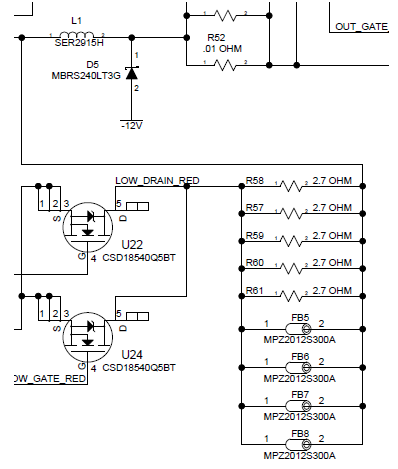
I'm reviewing a colleague's LED driver design. He's basically copying the LM3434 eval module design. I'm trying to understand how part of the circuit is supposed to work. Basically, a bunch of ferrites and resistors are placed in parallel on the drains of the low-side MOSFETs.
What is the purpose of this arrangement? It seems to me that the resistors short past the ferrites, limiting whatever high-frequency filtering the ferrites offer.
Can anyone enlighten me, please?
Cheers!
MADman