This thread has been locked.

If you have a related question, please click the "Ask a related question" button in the top right corner. The newly created question will be automatically linked to this question.

BQ78350 FETs disabled and alert pin behavior

Other Parts Discussed in Thread: BQ76940, BQ78350

Hello!

We have design a BMS circuit for a 14S battery pack based on BQ78350-BQ76940 chipset.

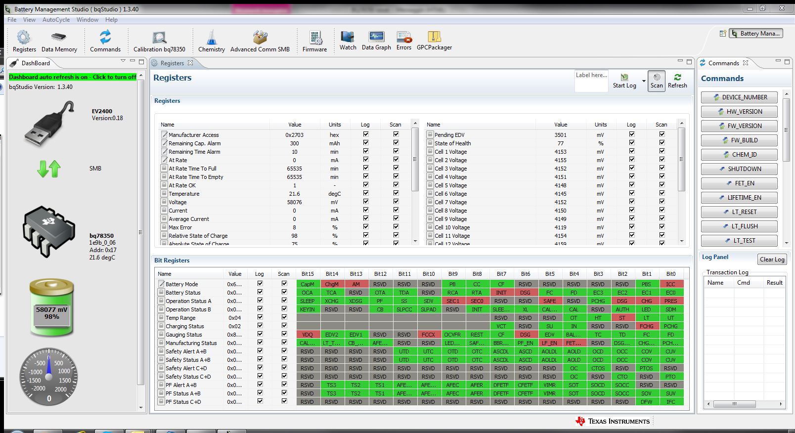
After assembling BMS circuits on battery packs in our production line, we experienced several failures (about 1-2% over some hundreds of products). In particular failed systems appear with FETs disabled, but there are no other evidences into registers map about any specific and wanted state (if we compare the registers map of a normal system with a failed one, only CHG and DSG flags into the Operation Status are different). These are two screenshot examples of a failed and normal systems:

Failures was observed into several steps of the battery pack assembly and in particular we found some of them after leaving systems at rest (before testing or also after finishing and sealing operations) or after the overcurrent test (in this latter case only the DSG FET was permanently into the off state, but no overcurrent protection flags were active).

By investigating on this problem we found some potential issues related on the alert pin.

On our board the alert pin is connected between the BQ76940 and BQ78350 by following a quite long path (our board has a particular form factor and it was very difficult to avoid this). A 470k pull-down resistor is connected very close to the BQ76940 pin, while a 1nF capacitor is connected quite close to the BQ73850 pin. During the design phase we used a 470k resistor because the 1M recommended value led to some problems (FETs permanently disabled) and also because a similar value were used into the "typical application" schematic.

Currently on the Alert pin we see different type of waveform, also on normally working systems:

  1. alert signal 1: continuous pulse train with increasing duty cycle
  2. alert signal 2: sequence of: 10s fixed low level, 3 pulses like above (each time the pulse duty cycle increases), about 10s fixed high level

We cannot understand why there are so different signals and which one is the correct one. Maybe both of them are ok (systems properly works in both cases), but it is strange to see so different situations.

Moreover we tried to recreate the failure by forcing a pull up (10k to 2.5V Vcc line) on the alert line, in order to simulate a disturb that can be coupled on such a line. Well, we observed two different reactions:

  1. if the pull-up in applied only for some second or for a few tens of seconds, FETs are only temporary disabled and they are enabled again after few instants after removing the pull up
  2. if the pull-up is applied for several tens of seconds (we don't know exactly the threshold value compared to the previous situation), the system enters into an halted state with FETs disabled and no evidence of any particular state into the registers map (except CHG and DSG flags disabled).

The latter one seems to be exactly the failure we experienced on our products. Unfortunately it is unrealistic on our products the Alert line was intentionally or accidentally pulled up for a so long time. So we would like to ask to any expert:

  • is that correct there is a similar behavior if the Alert line is forced high?
  • why there is a different behavior if the Alert line is forced high for a short or a long time?
  • is it possible that a short disturb on such an Alert line can lead to a permanently halted situation with the only evidence of FETs off and no other information?
  • if yes, is it possible to try to fix this problem by reducing the pull-down mounted resistor? which is the limit for the pull-down resistor?
  • otherwise, could the 1nF capacitor create any critical situation? should we change it?
  • more in general, do you have any idea or suggestion about the problem of our failures (also not related to the Alert pin)?

I hope in a kind prompt answer because we have to solve as soon as possible this problem.

Thank you very much for your support

Best regards

Matteo

  • Hello!
    Some updates concerning this issue...

    Unfortunately we received no answers to this post, so we had to make several more investigations by ourself.
    We found the 2 reactions of the system we mentioned into the previous post to a forced pull-up of the Alert line are not related to the duration of such a pull-up phase, but it is (at least apparently) random. The pull-up phase can be long or also very short (just a pulse) and the system seldom stall into the mentioned state, i.e. with FETs opened.
    Such a behavior happens also with a very low pull-up resistor so that also a simple finger can induce the problem.
    In this case it could happen that on our production line the operator can touch the electronic board on the alert line and randomly create the problem on some pieces.

    We found also a sample where such behavior was very frequent, so we could go ahead with our investigations.
    We tried to make some trials on such a sample for reducing the Alert line sensitivity to the pull-up disturbance, but we didn't find any reasonable value of pull down resistor and filter capacitor on the alert line suitable for mitigating the problem: there was no possibility to work on the only 2 external components connected to the Alert line.
    So we got to the conclusion that the problem is not related to any external phenomena, but it is only due to any internal behavior of the BQ78350. Its state machine maybe is very sensitive and can stall if some kind of disturbance is detected on the alert line.

    The only possible solution to the problem was to look for any firmware update or fix for the BQ78350. We used the R1 firmware for updating our non-R1 BQ78350 and for the sample with the frequent stall behavior such a problem disappeared (we tried some times to switch back and forth between firmware versions and we obtained always the same result: with the old version we experienced the problem, with the R1 version the problem disappeared).
    Currently we have reprogrammed a batch of our production with the R1 firmware and we are testing them for checking if the firmware upgrading is a good solution and can avoid any stall on pieces on our production line.

    We would only ask to some experts or TI engineers if our analysis can be correct and we can hope to have found the solution to our problem.
    - could some kind of disturbance on the Alert line lead to a stall of the BQ78350 with CHG and DSG lines permanently fixed low?
    - could this problem be related to a firmware issue (bug, unpredicted state, ...)?
    We have no enough elements, information or detailed knowledge about this chipset for completely validating this solution.
    But we have a production issue to be closed!

    Thank you in advance for any confirmation or any support.

    Best regards

    Matteo
  • Matteo

    I am sorry for the slow response, but we have been out of the office for the holiday. I will review your data and provide a comment as to what may be causing the problem. I will try to get to it tomorrow. 

    Tom

  • Hi Tom,
    I'm still waiting any feedback from you...
    Have you got any update/confirmation, please?
    In the meantime I upgraded all our BQ78350s to the R1 firmware version, in order to go ahead with production, but any support to give us more confidence will be appreciated.
    Thank you very much

    Matteo
  • I never received any promised feedback and support from TI and in the mean time I found a still more serious bug of the BQ78350 non R1 version.
    I'm talking about a possible serious bug of the non R1 version because:
    - the problem described into previous posts never happened again after the upgrade of the firmware to the R1 version
    - the new problem I'm going to report below has been fixed by upgrading the firmware to the R1 version
    So it seems quite clear the problem is not related to any wrong use of the component, but to a TI firmware issue.

    The new problem I encountered consists of the definitely lock of the system with discharge MOS in off state in some cases after a short circuit operation (which can frequently happen in our application, also because of the inrush current of the load). The system remains into a state with no active protections (no flags in any status register provide such an information), but the discharge MOS remains definitely off and so, practically, the BMS is failed from the user point of view. In fact the only way to restore such a MOS is to reset the system (by means of a proper command or the specific pin), but not in all application the user can do it.
    I didn't investigate so much this behavior because my first tentative of solution, i.e. the firmware upgrade to the R1 version, has been successfully.

    Because of the silence from TI about these issues (i.e. totally missing of an official support!), I would like to post this information so other developers maybe can find some help if they encounter the same problem.
  • Matteo,
    Thank you for the comments. We have not been able to replicate the problem where the bq78350 does not clear the shorted load fault after it was reported and there were not firmware changes in the -R1 update to address it. The fact that the -R1 firmware seems to have fixed it must be a side effect of another firmware change.

    Do you still have the ALERT pin problem? The ALERT signal was recommended to have approx a 250 us max time constant (500k and .5 nF for example) it sounds like you have twice that so with tolerance the AFE may sometimes see ALERT as high after it is cleared due to slow fall time of the signal and set OVRD_ALERT fault turning off FETs. That AFE behavior can’t be masked. There were a couple of bug fixes in the -R1 firmware with handling and clearing alerts, so one of them may have changed the performance if the issue is no longer present.

    Tom