This thread has been locked.

If you have a related question, please click the "Ask a related question" button in the top right corner. The newly created question will be automatically linked to this question.

LED driver circuit sugesstion

Other Parts Discussed in Thread: TPS92630-Q1

TI,

From the specification, Vin range is from 5~40V.

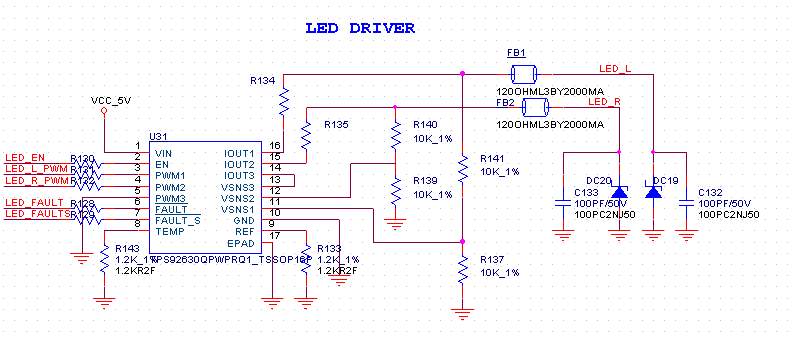
Now we connect to 5V, is there any risk about this connection ?

And we have problem on Iout pin, what is the maximum value of this pin ?

From datasheet it is 7V, and recommend value is 5V.

Kindly help to check, it seems not boost.

I posted this issue for schematic advice a few weeks ago and no one reply...is this a risk part ?

  • anyone can reply this issue ?
  • Why no one can reply this urgent issue?!

    Another issue is as below:

    We found the spec file didn’t provide the input maximum frequency of PWM signal.

    From our measurement of the EVM we found the maximum control frequency is 40KHz.

    This frequency is too low to let our DSP control the LED driver.

    Do you have the actually spec of the PWM frequency?

  • Hi Jacky,

    Sorry for replying late. Could you help to update the application information? Seem it is not used in the automotive rear lighting.
    Actually TPS92630-Q1 is a linear LED driver, which means the output voltage must be 0.9V (DROPOUT VOLTAGE which can be found in the datasheet) smaller than the input voltage to keep the output current constant. For your circuit, I noticed that the output current is 100mA/channel, is that right? May I know the spec of the R134,R135,FB1,FB2,DC19,DC20? And do you need single LED short function? Because single LED short function is not available when input voltage is smaller than 9V (VSNSX spec in the datasheet), recommend to connect VSNSX directly to the Iout. For the PWM dimming frequency, recommend not larger than 2kHz, because the delay time will cause non-linearity in the output current.
  • Hola Anda,

    Thank you.