Because of the Thanksgiving holiday in the U.S., TI E2E™ design support forum responses may be delayed from November 25 through December 2. Thank you for your patience.

This thread has been locked.

If you have a related question, please click the "Ask a related question" button in the top right corner. The newly created question will be automatically linked to this question.

UCC28180 Feedback stability

Other Parts Discussed in Thread: UCC28180

Hi,

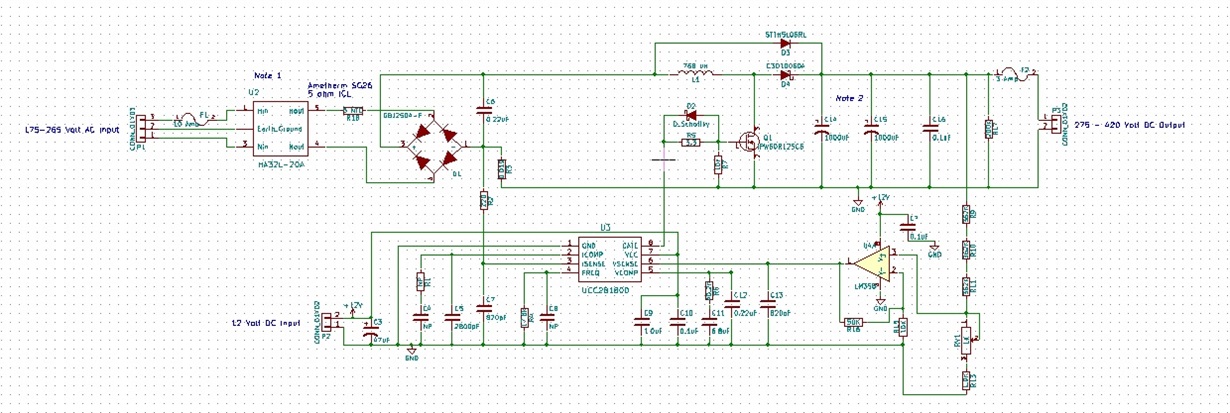
Can anyone tell me if this feedback to VSENSE will work.  U4A is set to boost voltage divider feedback by 6 times. I'm worried about stability. I figure the UCC28180 is designed to regulate output voltage +- 5%.  I'm asking for something more like +-0.83% output voltage.  The load will be resistive with only very small changes over time once voltage is set.

Thanks,

Dan

  • Hello Dan

    This arrangement should work in the steady state - ie once it gets up and running. You will need to adjust the components at VCOMP to take account of the added gain stage but that should be relatively easy. I think that getting this system starting up and shutting down correctly. The sequencing of the VCC rail to the amplifier and the way its Vout behaves during startup and shutdown will be critical. Note that pulling VSENSE to ground will give a shutdown the UCC28180. Ideally the op-amp output would do this for you by setting its Vout to 0V -


    The UCC28180 offers a 1.4% accuracy at 25C and 3% over temperature (Vref spec in the Electrical Characteristics table). These are ±6 sigma statistical limits and individual devices may offer the accuracy you need without the complication of an external amplifier. Whether this is an option or not will depend on the quantities you plan on building and on the operating temperature range you expect.

    Regards

    Colin

  • Hey Colin,

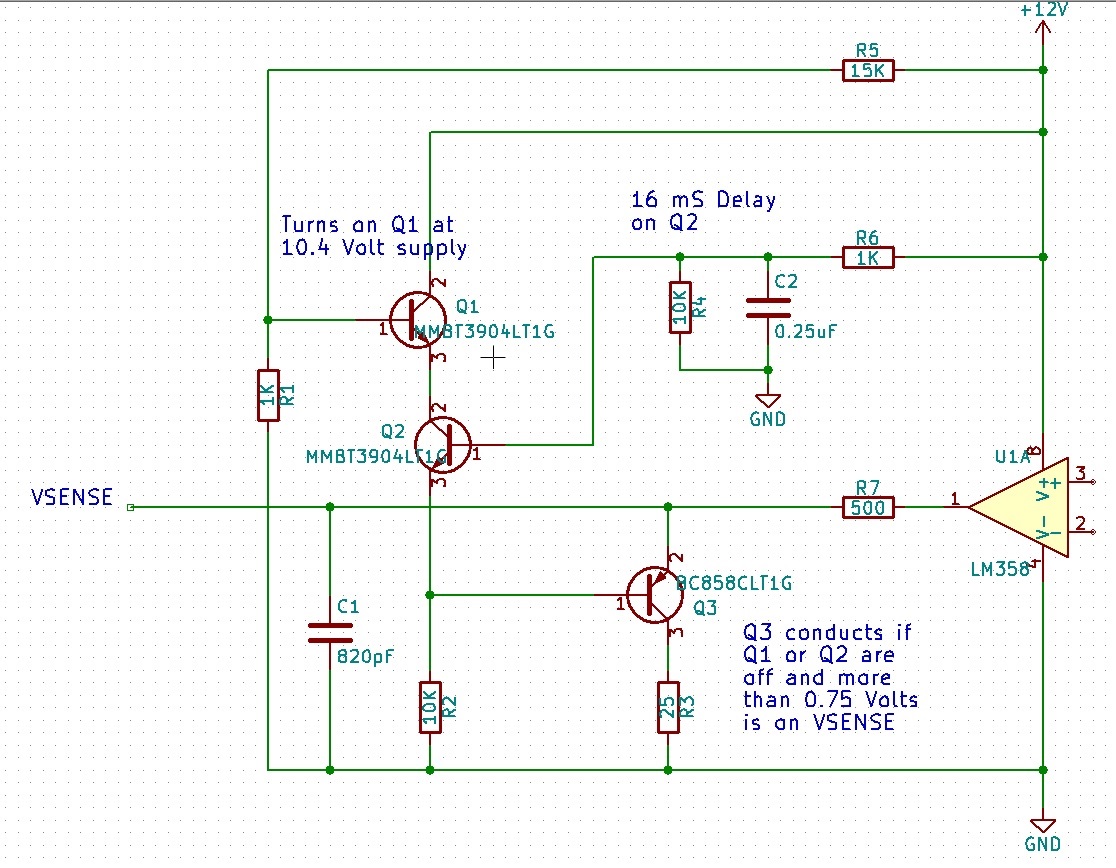
    I thought about it a little and this is what I came up with for pulling VSENSE to ground on startup and shutdown. I may have to adjust the values.  It was this or delay the UCC28180 turning on to give the opamp time to power up and the output settle. 

    With delaying the UCC28180 timing on idea. If I delayed it say 20 mS or so. That would give the opamp enough time to start and settle? On powering down the UCC28180 would turn off at 9.5 volts which is well within the operating voltage of the opamp? So, the opamp shouldn't do anything crazy when the UCC28180 is still on? unless you're worried about ringing? If so, I could add a 6 volt regulator to power the opamp that way there is not chance of VSENSE seeing more than 6 volts.

    Thanks for the help,

    Dan

  • Hello Daniel

    Sounds like you are on top of things here. The general rule is that steady state conditions are never (well almost never) going to cause real problems - the real issues arise from transient conditions - things like turn-on, turn-off, load steps, Vin steps etc, etc...

    Regards

    Colin

  • Hey Colin,

    When your talking about "adjust the components at VCOMP to take account of the added gain stage" . If I understand how this part works. I should reduce the size of the capacitors to reduce the reaction time on VCOMP?   

    Thanks,

    Dan

  • Hi Dan

    The way I see it, is you plan to add a x6 gain stage in the voltage feedback loop or an additional 15bB. If you want to keep the cross over frequency the same and assuming a single pole roll-off at -20dB per decade then the pole will have to be moved down by 0.75 decades. Lower pole frequency implies a larger capacitor - by a factor of 1/0.75.

    I'm assuming that the added gain stage has a bandwidth which is large enough that it acts essentially as a fixed gain with negligible added phase shift for the frequency band of interest - ie below the loop crossover frequency.

    Regards
    Colin
  • Hey Colin, You've helped me get to the point were I'm comfortable building a prototype. This there a reason to keep the cross over frequency the same? On the UCC28180 Design Calculator Tool line 255 lets me change Fv. It only seems to change the value of Cvcomp, which seems to be what your talking about. Am I on the same page?

    Thanks,
    Dan
  • Hi Dan
    You want to keep the cross over frequency more or less the same - the main thing is that the voltage loop cannot have significant response at twice line frequency because if it did it would try to regulate out the voltage variations at twice line frequency and your power factor would drop significantly. So - normally the cross over frequency for the voltage loop is set at around 10Hz -

    Changing Cvcomp is the right thing to do - probably increase it by a factor of 1/0.75. Having said that - the voltage loop is so slow in any case that you should have lots of margin.

    Regards
    Colin
  • Hey Colin,
    You've been a great help. It's support like this and good examples in the datasheets that makes it easy to use and buy TI products.
    Thank For all your help,
    Dan