This thread has been locked.

If you have a related question, please click the "Ask a related question" button in the top right corner. The newly created question will be automatically linked to this question.

LM5050-1 noisy output issue

Other Parts Discussed in Thread: LM5050-1, LM5050-2, LM25117, TPS2410, LM74610-Q1

I have the LM5050-1 connected exactly as described in the datasheet, but am seeing very noisy output when the voltage goes above 17V.  Up to that point, it works and maintains ~20mv across the FET, but once I reach the 17V threshold, the roughly 2.6V gate drive drops to around 0.9V and has 2V of sawtooth noise at roughly 800 hz (the frequency is not stable) on it, and the voltage across the FET increases to roughly 0.5V. 

I have tried the following:

I added the 100 ohm resistor and 0.1 cap going to Vs (Vout and Vs were originally tied together)

I added a 100 uF cap at the output

I changed the 0.1 uF cap on Vs to 4.7 uF (ceramic MLC)


Each of the changes improved things a bit, but none have really solved the issue.  This circuit has to operate at 27.6V (2 SLA batteries)

I am trying to change to this part from an LTC ideal diode controller, but so far its not looking all that promising.

  • Hi Duane

    I think your post belongs on the power interface forum. I will move it for you.

    Regards

    Peter
  • Some additional thoughts on this issue:

    With an input of 27.6V (to match up with 2 SLA batteries), the gate waveform is a sawtooth, with the rising edge being slow and the falling edge being almost instantaneous. (I could send a screenshot of my scope if that would help)  This would lead me to believe that the problem is that the chip is momentarily detecting a reverse voltage condition and pulls the gate drive hard low, then the 'condition' goes away, so the gate voltage once again rises to try and turn the FET on, ...  That having been said, the extra filtering I put on (the 100 uF cap right at the output of the FET as well as additional filtering on Vs, should have resolved the problem.  I can't identify a reason for the issue. 

    Could this be a defective lot of parts that are hyper-sensitive to noise?  The circuit has this problem with a load of about 200 mA as well as a 1-2 A load.  If the problem were noise, I would think either light loading or heaver loading would affect the way it works.  I have also tested it at roughly 15A (the FETs can handle in excess of 60A, and have <1mohm RdsON), but the FETS get very warm because the only thing conducting is the body diode.

  • Hi Duane,

    Welcome to the E2E forums and thank you for considering our product for your design.

    If you can share any schematic or waveforms, it would help us troubleshoot the issue much faster.

    You can click the "Use Rich Formatting" text on the bottom right-hand corner of the reply box. Then there will be options such as "Insert Picture" or "Insert File".

    However, it sounds like the circuit is being very sensitive (as you have indicated.

    We have one app-note on this subject which may be of interest:

    However, the main point of the app-note is that adding capacitance to Vout should help (as you have tried).

    If this does not resolve the issue, there is another option.

    Overall the LM5050 features an extremely fast reverse current response (the spec is a 50ns response time). However, this can lead to nuisance shutdowns in systems with some level of noise.

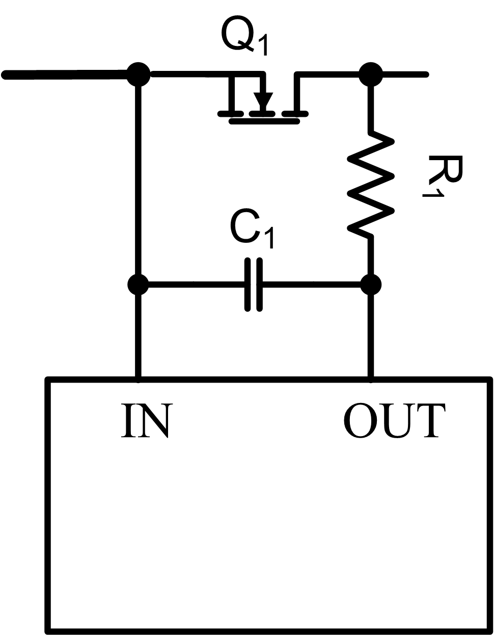
    As a result, we would recommend adding some filtering to the sense lines themselves. Please refer to this image below:

    So this would create an RC filter which would help prevent nuisance trips due to noise.

    For example, you can try an R of 10ohm and C of 0.1uF to create 1us of filtering which may resolve all the nuisance trips.

    If 1us of filtering is too much for your system (you want a faster response time for reverse current shutdown), then you work down and decrease R and C.

    Thanks!

    Alex

  • Hi Duane,

    I saw your note at the bottom that the MOSFETs have <1mohm of Rds-on.

    Note that the LM5050 is a regulation mode ORing controller, not hysteric. A simplified explanation of the LM5050 regulation loop works like this:

    If Vsd > 22mV, then increase gate voltage

    If Vsd < 22mV, then decrease gate voltage

    If Vsd <-28mV, shut down gate immediately.


    So if the load is just 200mA for example and the Rds-on is 1mohm, then the Vsd would only be 0.2mV. The gate voltage will keep decreasing, therefore increasing the Rds-on, until the MOSFET is right on the verge of shutting off.

    I agree that at higher currents, the gate voltage will be higher and less prone to shutting off.

    Overall it may help to use a MOSFET with higher Rds-on. Section 8.1.1 of the datasheet discusses MOSFET selection. It depends on the current range of the application:
    www.ti.com/.../lm5050-1-q1.pdf

    If it is a 0-10A application, maybe a 5mohm to 10mohm MOSFET. If it is a 10A to 30A application, maybe a 3mohm.

    Thanks!
    Alex
  • Alex,

    This looks like a great solution.  I'll implement it, then post whether or not it fixed the problem.

    The FETs were chosen based on the circuit design constraints.  I am driving a motor to control a fire door, so it has to be able to supply >30A without excessive heating.  I have it set to trip at roughly 45A, although typical currents are much lower at around 17A or below.

    When the LM5050 is working, it controls the Vds very nicely with around 2.6V on the gates at low currents, going higher as the current increases.  The two FETs are used to achieve the higher reverse-breakdown voltage required, since the FETs breakdown is only 40V, and R117, 118 are used to force any reverse voltage to divide evenly.  Note - the schematic shows a LM5050-2 part, but the circuit is, in reality, designed for an LM5050-1, and both resistors should be 10K.  The circuit, as built, is correct.

    Duane

  • Hi Duane and Alex,
    Did Alex's RC network solve the unstable GATE pin? Unfortunately the RC has not worked for me. I also observe a 2 to 4kHz sawtooth on the GATE pin, which varies/disappears with various load currents. I have a 0.1uF 0805 chip soldered directly across the OUT and IN pins. I tried a series 10-ohm and then a 100-ohm to the OUT pin. Then I added a second 100-ohm in series with the IN pin. My connection parasitics are minimal using 0402 parts. The filtering seemed to shift the load current levels where the Reverse comparator triggered, but never solved it. Placing filter caps to power GND at the MOSFET inputs and outputs have similar effects.

    My board has a pair of LM5050K-1's and AON6284 MOSFETs, used to switch a pair of 14-28V 10-amp batteries into a 12V Buck switcher (LM25117 running at 200kHz). The buck's input caps (6x10uF chips) are placed 20mm from the LM5050 & MOSFET outputs. When I disable the Buck, and place a electronic load on the buck's input caps, the LM5050 seems to work fine (about 24mV across IN & OUT pins) at load currents 0 to 6 amps. My board also has a second pair of LM5050K-1's for the DC output, which OR the output of the 12V Buck with an external 12V ACDC supply input. The DC output pair seem to work fine, and are not disturbed by the Buck switcher noise. All four LM5050s each have their own tiny GND island with a single GND via to the main plane, and are placed away from the buck circuit and its ground loop.

    Thanks for any suggestions.

    Norbert
  • Norbert,

    It worked great for me.  I experimented with a smaller cap, but a .01 caused it to oscillate again.  The challenge is that the more filtering you put in, the slower the reverse shutoff becomes, so I had to find the 'sweet spot' for my circuit.  Given the type of circuit you are driving, I would suspect that even more filtering will be required.  You could try something ridiculous (4.7 uF, which is readily available in MLC, for example), and if that stops the oscillation, then it becomes a matter of finding the smallest cap that will do the job.

    I also put in the 100 ohm and 0.1 cap on the power (Vs) pin.  If you are using a -2, then that option isn't available to you, but otherwise, it seems like cheap insurance.


    I hope this helps.


    Duane

  • Hi Norbert,

    Welcome to the E2E forums and thank you for considering TI devices for your design!

    I would be glad to help. To offer the best assistance can you please post your question as a new thread? Our whole team gets an email whenever a question is posted, so we can offer quick assistance.

    Duane,

    I'm happy to hear the RC filter helped solve your problem, and without adding too much of a delay. Thanks for sharing your experience and insight with the community here.

    Thanks!
    Alex
  • Hi Duane,
    Thanks much for quickly responding the other night. Upon your note, I decided to over-night several LTC4357 to try, and after much testing today, I have concluded they solved my problems. I had been struggling with the LM5050 for a few days, and actually had already tried the RC networks on the VS, OUT & IN sense pins before finding your and Alex's postings. I dead-bugged several LTC4357's on my board without the added decoupling caps and RC networks on the VS, IN, and OUT pins. They work great with no issue while my 200kHz buck switcher outputs 12V at loads from 0 to 12 amps. The MOSFETs remain fully enhanced which I never saw with the LM5050. My board uses 4 of these parts. I would have liked to use the TI parts (lower cost, etc.), but it also has a reverse leakage issue which I also found the LTC part does not have, causing several mA of leakage current from my batteries (when IN is floating without a battery input, and VS & OUT are powered from the other battery output). I probably could have accepted that leakage, but now I do not have to.

    Thanks again for your quick reply.

    Norbert
  • Hi Norbert,

    We greatly appreciate your feedback and thank you for taking the time to share your experience.

    The LM5050 "features" a 50ns response to reverse current, but as you have experienced it can be too fast/sensitive for some applications and lead to nuisance trips. That is where the RC may help.

    We added the leakage current note in several places within the datasheet to ensure customers are aware of it, in case they have a battery application where 3mA may be a concern.

    That being said, if we end up releasing a new high voltage ORing controller, it will not have these issues.

    For low voltage applications, the TPS2410 family of devices do not have leakage issues and the TPS2410/11 havea dedicated filtering pin.
     
    Thanks!
    Alex

  • Norbert,

    Another part you may want to check out is the LM74610-Q1. It has zero quiescent current and would work well in your application with a lower cost compared to the solution you are considering.

    Mathew
  • Hi, Norbert,

    Interestingly enough, my 5050 circuit is to replace the LTC part.  I have had MAJOR issues with it not starting up every time (3-5% typically), and LTC's tech support was less than helpful.  Hopefully you have better luck.  Perhaps LTC has re-spun their part and it now works reliably, but that certainly wasn't my experience.

    FYI, the symptom of the problems I had was that I would turn the circuit on, and every once in a while it just wouldn't turn on, so all the current went through the MOSFET body diode.  My application is in life safety, so unreliable operation simply wasn't an options I could live with.


    I wonder if an inductor at the output of the LM5050 ideal diode circuit would help to prevent the issue....

    Duane

  • Hi Mathew and Duane,
    Mathew, thank you for suggesting the LM74610-Q1. It has a couple concerns which we would need verifying in our application: the charge pump not starting up at low load currents and the 98% operating duty cycle. Also its larger 8-pin package than the LM5050 would have further impacted PCB layout. Since the LM5050 noise sensitivity issue delayed our final PCB release, we are in the critical path for production schedules. We decided a board re-spin with the similar sized LTC part would be fastest. We use qty 4 with operating levels from 12 to 34V, at loads 1mA to 10 amps. I may order a few LM74610-Q1 to test for a future board revision and/or new designs.

    Duane, thank you for warning me about the LTC not starting up reliably. You have me worried since I only "dead-bugged" one board which shows no issue. We will ensure production tests will catch if one of the 4 devices on the board has extra voltage drop. Unfortunately, you may be indicating the problem is intermittent at power-up, and we may never catch potential field problems. The coil idea may be able to help, but DCR power loss is an issue with 10 amps in our application. Thank you again for your past experiences and help.

    Norbert