This thread has been locked.

If you have a related question, please click the "Ask a related question" button in the top right corner. The newly created question will be automatically linked to this question.

Oscillation on output of Buck converter of TPS65000EVM demo board

Other Parts Discussed in Thread: TPS65000

Hi,

In our application we are considering to implement the TPS65000. The buck converter is used to generate 4.0V from a 5V input voltage. In order to obtian 4V output voltage, R3 is changed to 82k on the eval board.We currently see an issue that will prevent us from designing-in this part.

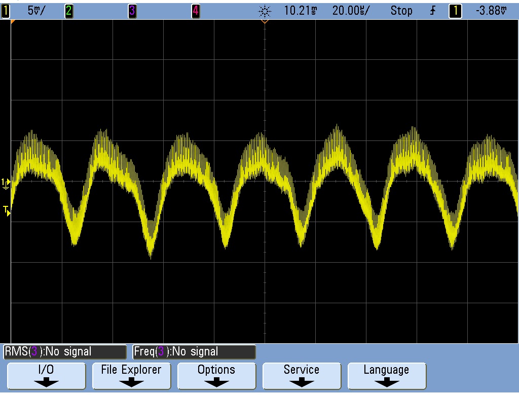
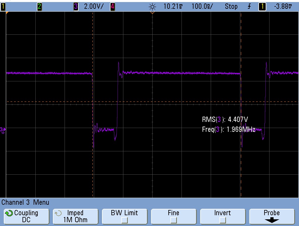
There is a oscillation of approximately 30kHz with an amplitude of 20mVpp on the output. It is more or less independent of the load that is applied. Does anyone have ideas how to solve this ?

Thanks.

Best regards, Stephan Manders


  • Stephan,

    I will take a look at this in the lab and get back to you.

    Janice
  • Stephan,

    Could you please also provide a oscilloscope shot of the SW , Vout, and Vin pins. Did you only change the resistor value? Inductor and capacitor values are all same ?

    Janice
  • Hi Janice,

    Thanks for your assistance. Please find the info you requested.

    The output voltage (AC coupled), 5mV / 20us/DIV :


    The switch voltage (2V and 100ns / DIV) :

    The output voltage (yellow) and the input voltage (in green) (5mV / DIV) :

    Some other findings :

    The amplitude of this effect is strongly dependent on the input voltage (4.8V is used in this case, it results in maximum amplitude).

    The only change done to the board is the value of the resistor in the feedback loop in order to obtain the correct output voltage

    Adding a 22uF ceramic capacitor to the 10uF on-board output decoupling capacitor does not have a significant influence

    Adding 2R series resistance in the input power supply line does not have significant influence (power supply voltage level is increased in order to obtain the same DC level on the input pins of the board)

    Changing the feedback reistors to 4k7 / 820R (instead of 475k/82k) does not have significant influence.

    Best regards,

    Stephan Manders

  • Stephan,

    This is due to the (SSCG) Spread Spectrum Clock Generation. This modulates the main-switching frequency, as it moves to lower frequencies the output voltage increases, and as it moves to higher frequencies the output voltage decreases. This is a feature of the part and is not a reflection of instability of the output.

    Janice

  • Hi Janice,

    Thanks for your quick response. In some applications (unfortunately in ours) this amount of LF ripple is undesirable and it would have been nice if the spread spectrum clocking could be disabled. In my view such properties of the device should be mentioned in the documentation.

    Best regards,

    Stephan Manders