This thread has been locked.

If you have a related question, please click the "Ask a related question" button in the top right corner. The newly created question will be automatically linked to this question.

BQ24600 - Hot Plug Failure

Other Parts Discussed in Thread: BQ24600

I am having an issue that is causing the BQ24600 to fail catastrophically when hot plugging a battery into the charge circuit when no adapter voltage is present.  I am using a high capacity Li-Poly battery that can source a large amount of current.  

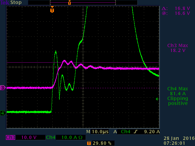
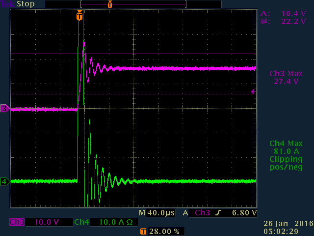
I initially thought that the failure was caused by a voltage transient caused by charging the ceramic output capacitors causing the battery voltage to rise beyond the absolute maximums of the part.  However, I have seen failures when the battery voltage is well within the tolerance of the part.  Below is a scope capture of my board failing when hot plugging in a battery to the output with no adapter voltage present.  You can see the battery voltage slightly ring when the battery is plugged, however, VBAT only reaches 18.2V prior to the failure.  Shortly after, the circuit failed and you can see an extremely large current spike as the IC failed which resulted in the current sense resistor to finally fail open, fusing the circuit.  

I have removed the 0.1uF SRP and SRN capacitors to ensure there was no current flowing to these nodes as noted in another post on a similar issue.  I ahve also reduced the output capacitance to Qty 2 10uF ceramic capacitors as well as trying to add a 47uF aluminium output cap paired with a 17.1V tranzorb, none of which has resolved the problem though it has severely limited the voltage transient.

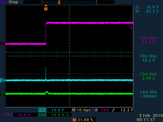
CH3 - VBAT, CH4 - Battery Current

Below is a screenshot using the same battery on the evaluation module.  The voltage transient is much higher than what I am seeing on my board, but the IC and sense resistor do not fail.  Therefore, I am not convinced the voltage transient is the root cause of the problem and perhaps some other portion of the circuit is causing the failure.

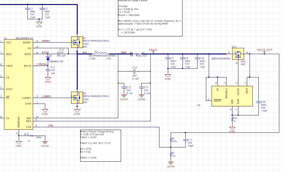
My reference circuit is below.  I am using slightly different FETs and I do not have a 4.7 ohm resistor from the D1 to the BTST node that is included in the evaluation module, but not the datasheet reference circuit.  But these are the only major differences I can see between the circuits.  I have adjusted the output capacitance to 20uF total ceramic capacitance matching the evaluation module with the same failure as shown in the scope capture above.  

Any ideas on what actions could be taken or scope traces I could capture to help isolate the issue would be appreciated.  The failure is catastrophic and I have damaged multiple boards which is making the issue very hard to debug.  

Thanks,

Alex

  • Hi Alex,

    Inrush current shouldn't be so high. You should verify that everything is soldered on the correct pins, and nothing shorted, especially around the FETs.
    Check V_adapter voltage, VCC voltage. If you can, check the current passing through the inductor by connecting one of the pins to the board through a wire.
    Check any other circuits attached to the board apart from this schematic.

    Thanks,
    Steven

  • Steven,

    Thank you for the quick response.  The second scope trace with the clipping 81 amp current is from the TI evaluation module with no other circuitry attached.  The first scope trace is from my circuit where you can see the inrush current is "only" around 40 amps, much less than the evaluation module.  This corresponds to less ringing on VBAT on my board vs. the evaluation module.  Again, all well within spec.  

    Prior to this failure, the board was working fine.  I am able to plug in an adapter, which charges all of the caps on the board with very little to no overshoot on the adapter input voltage.  I can then plug in batteries with no issue and charge them at 10 amps with no issues so I don't believe there is any underlying issue with board manufacturing or other pins that would be shorted as the failure would present itself either when an adapter was plugged in, or a battery was plugged in and began charging.

    The failure only occurs when I have a board with no adapter plugged in and the caps are uncharged.  Again, I am charging a fairly large 11Ah Li-Poly pack that can source a large amount off current (100's of amps over a short amount of time).  Using a voltage supply as a battery will not exhibit the same faults as it would not be able to source this much current.  

    But again, I have not gotten the evaluation module to fail even with the large inrush seen in the second scope trace using the same battery, so I do believe there might be something different on my board we are not seeing.  There is other circuitry on the board, but none of which is operating without an adapter voltage present and is isolated from the VBATT output.  

    I can measure the current through the inductor, but as I stated before, this is a catastrophic failure to my board.  So performing this test will almost certainly damage another of my CCA's.  I am having a couple of board that have failed previously reworked, but am hesitant to perform more testing on working boards unless I am looking for something very specific.  By measuring the current through the inductor, what would you expect to see relative to the IC that would cause it to fail?

    Thanks for your support,

    Alex

  • Alex,

    You can limit the inrush current of the battery by placing an inrush current limit circuit between the battery and the rest of the charger.

    An example is using a resistor in series to dampen the initial inrush current, and then turning on a P-FET through an RC delay to short circuit the series resistor afterwards.

    www.interferencetechnology.com/.../

    Thanks,

    Steven

  • Steven,

    I have looked at implementing this and have ordered some parts to test this in the lab.  How would you suggest wiring up the VFB feeback network? Ideally this would be wired in the same exact fashion as the reference design.  However, I plan on using an ideal diode controller for the bypass FET.  There is a voltage drop associated with this design that I would like to account for to ensure the charge voltage is set correctly and accounts for this voltage drop.  

    If I tap into the output side of the FET are there any issues with there being a voltage present on the VFB pin with the rest of the IC isolated and off?  See the attached schematic for one design reference.  This will only allow the output caps to be charged once an adpater is present.  


    Thanks,

    Alex

  • Alex,

    The VFB circuit is good. However, the charger will show a fault for battery absent as it will not detect the battery connected to SRN because of the battery blocking FET. A solution could be to turn on the FET with reference to input voltage with an RC delay (to allow enough time to charge the input caps), that way it turns on when the input is connected.

    Thanks,
    Steven
  • Steven,

    Thank you for the feedback.  I was able to successfully wire up a solution very similar to what you suggested.  I was not able to use the ideal diode controller I initially designed for as the controller I had selected in the previous schematic had reverse current protection and was shutting the FET off during the battery detection which was preventing a charge cycle as you mentioned.  

    I was able to implement a P-CH FET that was controlled by another lab supply.  Upon doing so, there was very little inrush for a very short amount of time when the battery was plugged in.  I am assuming this was caused by the time delay for the P-CH gate to reach the battery voltage and shut the FET completely off.  Once the Adapter voltage was present and the output caps were charged, the battery would start charging once I enabled the N-CH FET turning the P-CH FET fully on.  

    I have not decided how exactly I will time the turn on of the FET.  I have attached a reference schematic that will allow me to test 3 different ways once I relayout the boards: RC time constant, supervisor circuit and u-controller.  

    CH3 - P-CH Source

    CH2 - P-CH Drain

    CH4 - Battery Current

    Thanks,

    Alex

  • Hi Alex,

    Seems to me that you got the idea. The problem with having the 1k resistor at the battery is that you will have leakage through that resistor and will discharge ~17mA when you enable the NFET (connect the adapter in this case). If you are okay with losing 17mA of charge current then its good.

    You can turn off the PFET faster by reducing R55 value and adding a resistor to R56. You can also reduce leakage current by adding more resistance at R56.


    You can reduce the circuitry to just a resistor divider connected to the input voltage pin before the input diode (assuming NFET can withstand any voltage you apply to it after the divider).

    As for the capacitor for the RC delay, the implementation looks good at C38.

    Thanks,
    Steven