This thread has been locked.

If you have a related question, please click the "Ask a related question" button in the top right corner. The newly created question will be automatically linked to this question.

LM5101AM gate source impedance

Other Parts Discussed in Thread: LM5101A, UCC27201, LM5101, UCC27201A

Hi TI team

I am using LM5101AM in full bridge circuit.

During the gate source impedance measurement in circuit, some devices showed 2Kohm, which is normal where as some devices showed 25-35ohm only. This low impedance reading is exposing the vulnerability of the devices which could ultimately fail my unit.

Could you please let me know whether this is a known issue or please provide other explanation?

Best regards

Nabin 

  • Hi Nabin,

    I have asked one of the engineers from the driver team to look at this issue for you.

    Regards

    Peter
  • Hi Nabin,

    To answer your question, no, we have not seen this issue.

    Are you measuring gate to source impedance of power MOSFET being driven by LM5101A using hand-held multi-meter?

    if that is true, you should not see low impedance, unless power MOSFET is bad or gate is tied to gate drive transformer.

    Would it be possible for you to share schematic snapshot of the section you are measuring?

    Thanks for sharing your problem with us.

    Regards,

    Ritesh

  • Hi Ritesh,

    I am having this problem also. The LM5101A appear low ohm on pin 3 to pin 4.

    I using driver at negative side of my synchronous buck converter. I connect my VSS pin to -80V and my VDD is +12V above my VSS rail. 

    Will this harmful to the LM5101A? 

    My schematic attached. LM5101A.pdf

    Hope that you can help on this. I have quite number of drivers short at pin3 & pin4.

    Thanks!

  • Hi Kang,

    I am part of the same team as the op, and want to provide more detail to compare if our problems are similar:

    My issue is that for the high side driver after a power on/off event (I turn on and off our product), when I measure the Rgs (pin3 and pin4) of the MOSFET it is low impedance of anywhere between 5-50 ohm (using a Fluke multimeter). In comparison when I use the UCC27201 series of drivers for the same product after a power on/off event, if I measure the Rgs using a Fluke multimeter, the Rgs is the expected value of the resistor we placed there of 2kohm (for protection). This same issue happens if we change the Rgs resistor to 100k.

    Regards,
    Ryan Fernandes
  • Hi Ryan and Kang,

    I have asked our design engineer about difference in architecture of LM5101 and UCC27201.
    Meanwhile, would you please educate me more about providing any scope shots, timing diagram, schematic, etc.... to better help you.
    Would you do this one test for me?
    After power cycle and before measuring impedance, would you please discharge the VDD and VHB capacitors (and also the boot voltage if possible), and then measure the impedance.
    Is this low impedance intermittent or happens every single time you perform this test?
    Is power MOSFET damaged every time you measure this low impedance?

    Thanks and regards,
    Ritesh
  • Hi Ritesh,

    • After a power cycle if I discharge pin 2 and 3 to ground, using a metal short connection, then the impedance will properly show as the 2kohm resistor I placed across Rgs.
    • This low impedance happens after every power cycle.
    • The power MOSFET has not yet been damaged in the testing board, but from manufacture there have been many premature failures on the power stage.

    Regards,

    Ryan Fernandes

  • Hi Ryan,

    As I suspected, internal circuit might be staying biased and therefore you are measuring low impedance.
    During the re-bias, if the input pins are at correct state, there should be no performance issue.
    I believe one of the specification of the driver might be violated during the manufacturing test.
    I have also seen spurious failure when ESD is not well controlled through out the process.
    Does driver fail when the power MOSFET fails?
    It would be a good idea to send failed driver to TI for FMA to focus the investigation in right direction.
    I will let you know what I hear from my design team.

    Thanks and regards,
    Ritesh
  • Hi Ritesh,

    I have screenshots to show the operation of the driver in my circuit but how do I share them over this forum?

    Regards,
    Ryan Fernandes
  • Ryan,

    When you Reply, click the         Use rich formatting link at the lower right of the Reply box, you'll then see a toolbar at the top of the text box.  Clip on the paperclip to attach file, or the box to the immediate left of the paperclip to insert a graphic.

    ~Leonard 

  • Hi Ryan,

    Thanks for sharing the waveforms.

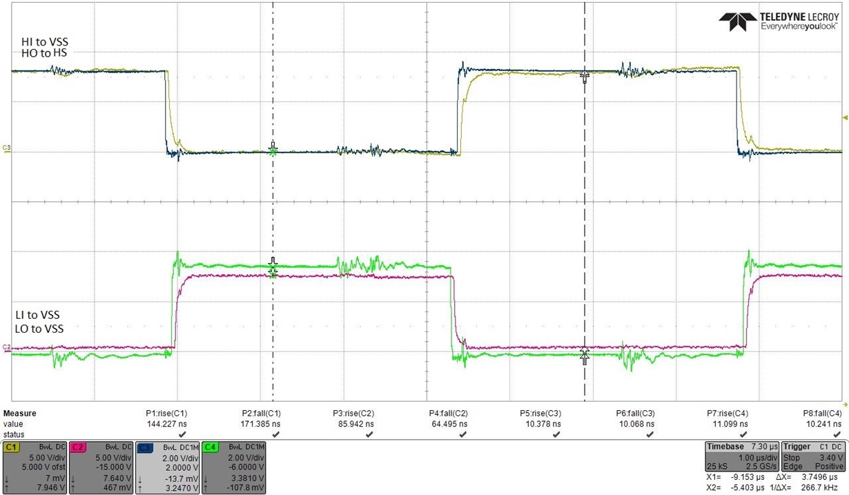
    I noticed that there is bandwidth limit on all of the waveforms. It is generally a good idea to take waveforms without bandwidth limit and with single ended probe.

    Differential probes do not have much of bandwidth and it is difficult to capture spikes using them.

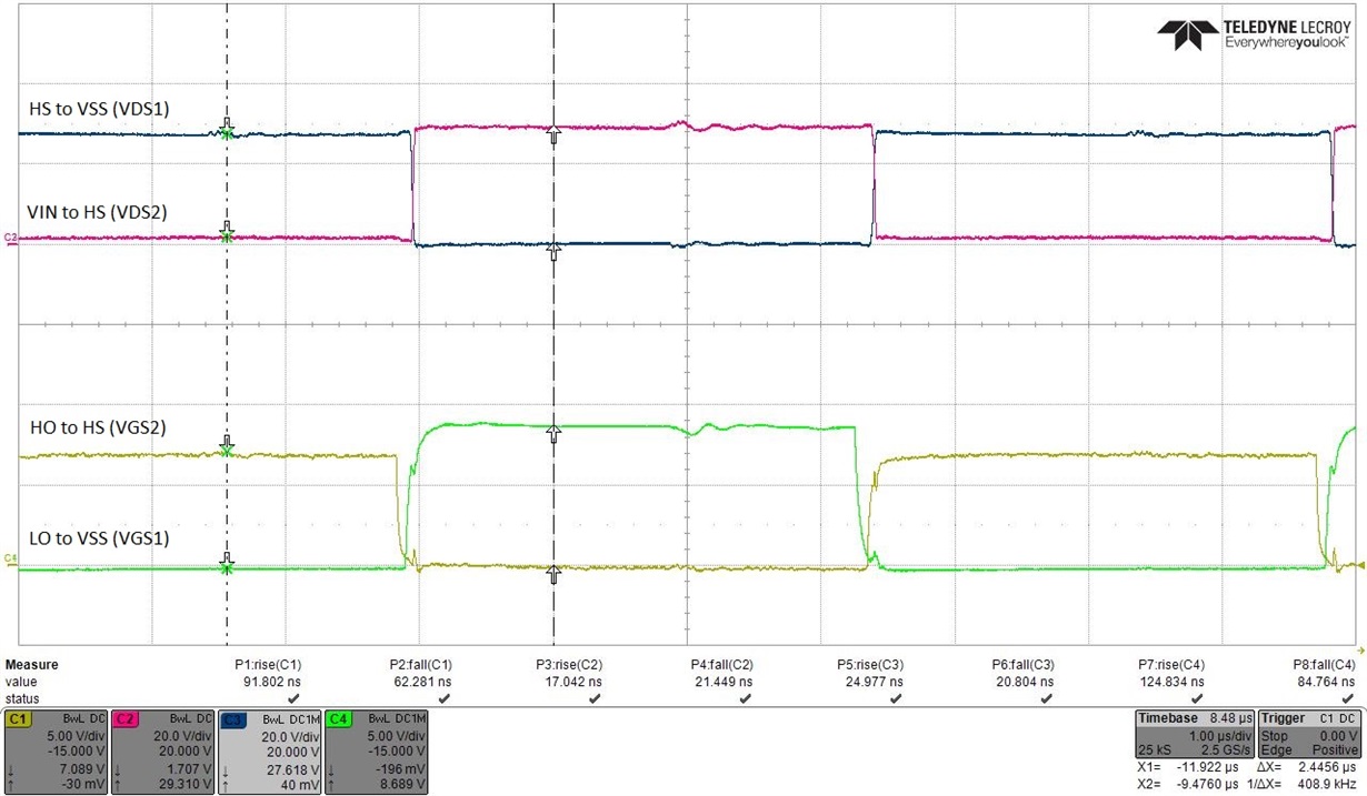
    From the last waveform, it seems that there is some cross conduction between high side and low side MOSFET.

    I believe this waveform is taken at steady state. It is possible that the dead time between high side and low side gate drive is not enough to prevent shoot-through in any and all operating conditions.

    I discusses the low impedance measurement with our design team.

    If you look at the LM5101A datasheet, you would see that when the driver is in UVLO condition, the output is held actively low.

    Even when the inputs are floating, the output is held actively low.

    It means that the driver state MOSFET internal to the LM5101A is turned-on in these conditions. Therefore, when you measure impedance across pin 3 and pin 4, you would measure Rds(on) of the internal MOSFET, which is in parallel with and much lower than 10k placed at gate to source of external power MOSFET. This impedance is also somewhat nonlinear.

    This phenomenon is the same when external power MOSFET need to be turned OFF in normal operating condition.

    Therefore, measuring low impedance across gate to source while power is turned-off, neither impacts reliability of driver nor reliability of power MOFET the driver is driving.

    Let me know if I could be of any other help.

    Regards,

    Ritesh

  • Hi Ritesh,

    Thanks for the information. Can you clarify why the UCC27201A does not demonstrate this behaviour if it is desirable, since it is a newer driver model.

    Regards,

    Ryan Fernandes

  • Sure Ryan.

    There are some applications where customers would like to guarantee that the output of the driver needs to be low when VDD and/or inputs are floating as they cannot afford external pull-down.

    Now as I mentioned before, the output stage of the driver is CMOS totem pole. To actively pull the output low, the internal NMOS has to be turned ON. When internal NMOS is turned-on, the HO to HS impedance would be dynamic ON impedance of internal NMOS.

    While in some other applications, it is ok to float the output (high impedance) when VDD and/or inputs are floating. The end application can afford a strong pull-down (such as yours with 2k). In those cases output stage of the driver do not need to be active and therefore HO-HS in those conditions would read what is external pull-down value.

    We had customers even asking for a fixed tri-state on the output, such as IGBT power stage customers.

    Think of it this way, the HO-HS impedance is low every switching cycle and would not cause any harm to the performance or reliability of the part.

    Let me know how else I can help.

    Thanks and regards,

    Ritesh