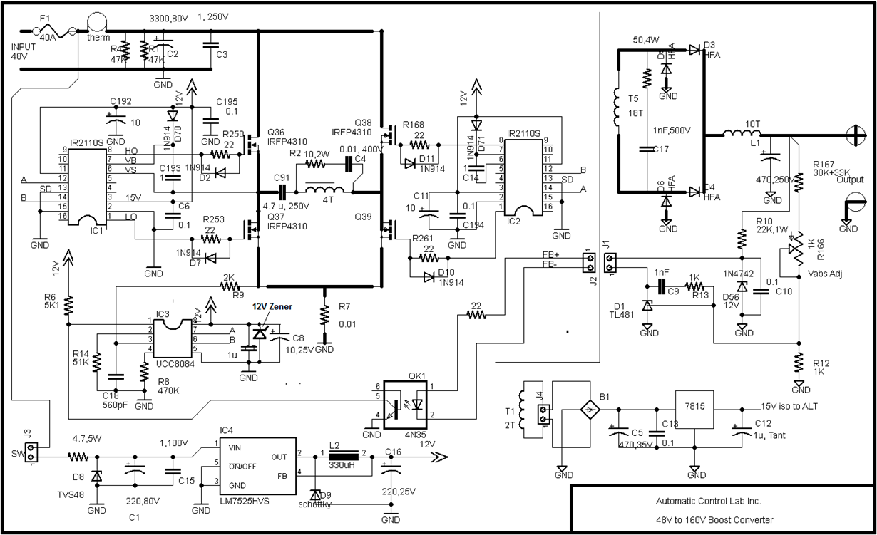
I am using UCC38084P PMIC for a 48V to 160V- 1.5KW Isolated Full Bridge DC-DC Converter (circuit diagram is attached).
This IC drives 4 MOSFETs (Full-Bridge) via 2 IR2110 Drivers. There is 0.01 ohm shunt for current sensing which connects to pin 3 via a 1K and 560pF filter. I also have a 47K slope comp res at pin 2.
All my signal grounds go to pin 5 (GND) of UCC38084. Also, signal grounds of IR2110s and the low side of the shunt and large input capacitor negative are connected to pin 5.. The Power GNDs (Sources of MOSFETs and high side of shunt ) go to COM pin of 2110s. Power GND and Signal GND are connect via the shunt only.
The control power is 12VDC which is taken from 48V input by a Simple Switcher locally.
The circuit works beautifully up to 1KW, as long as I increase the 48V input power, and 12V control power, together slowly up or down. However, when I keep input 48V power ON and switch the 12V control power ON or OFF, UCC38084 IC blows up instantly the first switch (pins 8 and 5 becomes short internally).
My load is several parallel 220V light bulbs up to 1000W. The problem happens at all load levels (even with a low 50W bulb load or no load at all).
If I short the 0.01 ohm shunt, and short pin 3 to GND, the problem goes away and the converter works perfectly on switch ON or OFF.
My questions are:
1. What causes this UCC38084 IC blow up? and what can I do about it? UCC38084 is the only component in the circuit which blows up. MOSFETS and IR2110s stay alive.
I do have good bypass caps (1uF parallel with 10uF across pins 8 and 5). I even put a 12V-1W Zener across 8 and 5. Nothing seems to help
2. Can I ever use this IC with resistive shunt at all? Or, do I need isolated current sense (CT or Hall)?
3. According to specs, pin 3 can go up to +6V. To exceed this level with 0.01 shunt, I need to have 600A load inrush which is impossible. I event put a 5V zener from pin 3 to GND . But it does not help.
Thanks for your help. Darius


