This thread has been locked.

If you have a related question, please click the "Ask a related question" button in the top right corner. The newly created question will be automatically linked to this question.

TPS54331 not Sourcing Current

Other Parts Discussed in Thread: TPS54331

Hi,

We have a 15V power source (LIPO battery) that we need to regulate down to 5V to power a BeagleBone Black (BBB) board.  Currently, we are testing the circuit with simple power resistors as our load (so as not to damage the BBB).  We designed the circuit according to the datasheet and get a clean 5.2V unloaded output.  As soon as we connect any kind of load (tested at 42mA (120ohm) and 1A (5ohm) loads) the output gets loaded down to anywhere from 0-3V. In any case, it is clearly not capable of sourcing the required current.  Relevant components listed below:


Schottky Diode: MBR360 (ON Semiconductor) 60V, 3A

Inductor: 10uH (Abracon LLC AIUR-06-100K) 5A


I should also mention that we are using electrolytic capacitors for the input and output bulk capacitance (against the datasheet's recommendation).  With smaller ceramic capacitors we get noticeable ripple on the output voltage.  In a past design using this same chip, the electrolytic capacitors did not create a problem.


We tried two different chips (both of which work in a separate circuit that regulates 15V to 12V) and have replaced the Schottky diode and inductor with (equivalent) known good parts.  We have tried many values for the output filter cap including both ceramic and electrolytic.  We designed expecting our BBB to typically pull 1A.  The BBB website recommends powering the board so that up to 2A can be provided.  Thus, we designed figuring a max 2A current draw.  The chip is capable of up to 3A so we figured this would be ok.


The one thing that kind of worked was replacing our 10uH inductor with a 39uH one that was in the lab.  This worked for lighter loads (got a clean 5V out for the 42mA load) but still did not work for the 1A load.  The inductor used was Bourns Inc. RLB9012-390KL


Perhaps we need a different inductor?  I'm not sure if this is indeed the case, but if so please advise as to how to select a proper inductor for the application.

  • I'll probably need to see the schematic and layout to start with. I highly recommend bypassing the input with a high quality ceramic capacitor. You can certainly use additional electrolytic on the input. As far as output capacitor is concerned, the TPS54331 is flexible. Just remember you need to change the compensation any time you change the output filter components. You very likely have ended up in an unstable condition. Can you provide waveforms of the switching node during stable output voltage as well as your faulty condition?
  • Hi John,

    Thanks for the reply.  Attached are the schematic and waveforms.  We are currently prototyping on a breadboard, so there isn't really a layout I can provide you.  We have everything grounded to the same breadboard rail which is connected to the ground of our power supply (we are using a 3A bench supply in lieu of our battery for testing).

    I don't have immediate access to very many ceramic capacitors in lab.  The largest we have is only a couple of uF.  I tried putting in a 10uF tantalum capacitor at the input but it had no effect.

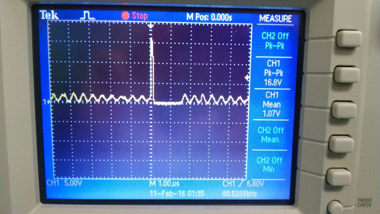
    The top waveform is the switching node while the system is unloaded (working).  At this point, the output is a smooth 5.2V.  The bottom waveform is when loaded with a 1A (5ohm) load (fault condition).  At this point, the output is 0V.

  • Generally speaking, you cannot usually develop these circuits on a breadboard. The circulating current paths need copper pour areas and usually you will need a ground plane. The compensation looks iffy. What is the ESR of the output capacitor? From your waveforms, you are for sure operating in DCM. What are the conditions for the two waveforms?
  • My RLC meter tells me that the resistance of the output capacitor is 2.88ohm. Eventually, we will be doing a layout for the design and sending it out to be done on a PCB. We were hoping to verify our design on a breadboard before sending it out to verify that it works. Also for clarification the floating 220uF cap is supposed to be the input bulk capacitance connecting Vin to gnd.

    I'm not sure what you mean about the waveform conditions. The top one is when the circuit is unloaded and we get a clean 5V out and the bottom one is with a 1A load but the output voltage is zero (or very close to it).

    What is the best way to develop the circuit if not on a breadboard? We really only have one shot (due to cost and time) at sending it out to be done on a PCB so I want to make sure our design works first.
  • I think one good way is to get an official TI EVM. You can modify it for your needs. 2.88 ohm seems rather high for ESR. Do you have the Mfr part number? I can look it up.
  • The part number for the output cap is: Panasonic Electronic Components ECA-1EM221. I looked at the datasheet on digikey but didn't see anything about ESR.

    As far as building the circuit on a breadboard, we currently have a separate working circuit using the TPS54331 that regulates 15V-12V on a breadboard. In that case, the output of the converter is fed through an h bridge and to a 12V motor. While we have had similar problems with that circuit, we have it working now and can attribute our original problems to the high inrush current of the dc motor.

    So we have positive experience with building this kind of circuit on a breadboard. Perhaps something is different in this case.
  • I did not mean to say that it could not be done, just that users often have problems with breadboard circuits.  Let me see if I can model your output filter and compensation.

  • Webench suggests:
    R3 = 26.7k
    C5 = 2200pF
    C6 = 56pF

    Try those and see if your circuit works better.
  • How precise do the values have to be?  I grabbed

    R3 = 26k

    C5 = 2200pF

    C6 = 50pF

    It improved the situation but it still does not work properly.  In addition to changing these components I added a 1uF ceramic cap at the input in parallel with the 220uF electrolytic bulk capacitor.  These two changes together produced a better result.

    It is kind of intermittent in its performance and the actual mean output voltage depends on the load current (i.e. output voltage is having some dependence on output current).  In any case, it usually looks something like this at the output though the mean will be different depending on the load.  Here, it is obviously too high at almost 5.7V.  Also, the ripple is far too large for this application: