Hello all TI users!
I have a little problem that I hope to resolve with the help of local gurus :)
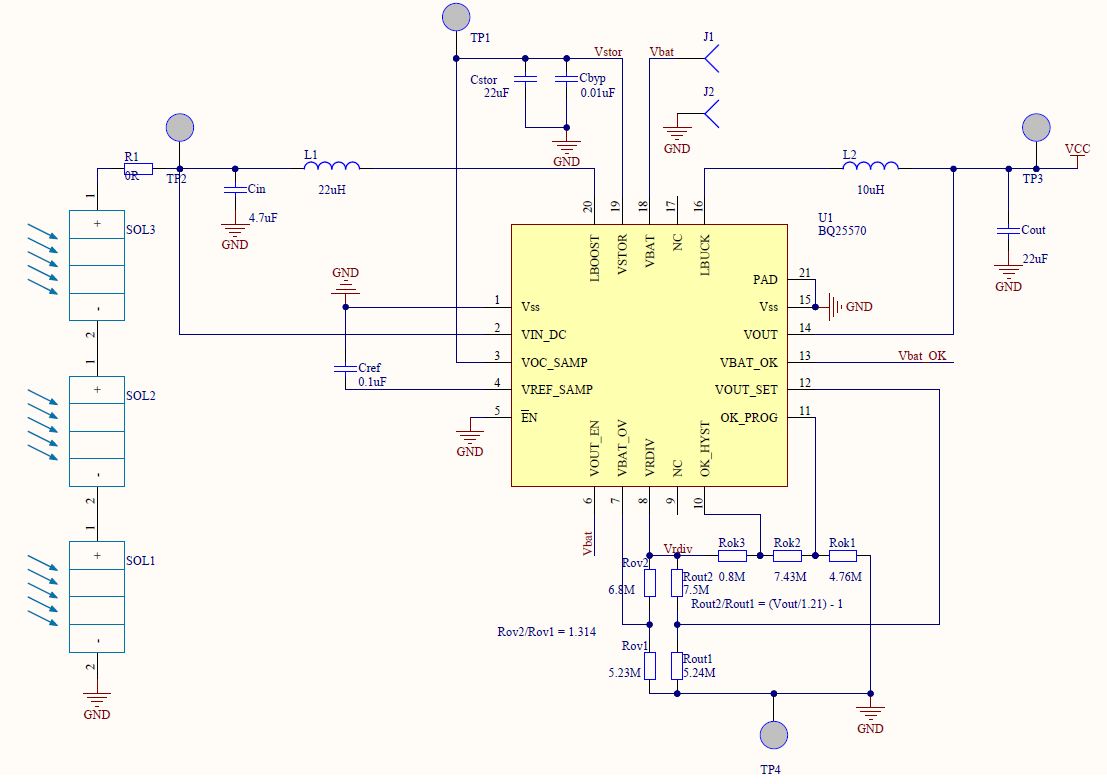
I have a board with BQ25570 and solar cells. My schematics is very close to the datasheet's typical solar application circuit.
A Li-Poly 240mAh battery is connected to Vbat. Three solar cells from IXYS (KXOB22-04X3L, 1.5V, 15mA) are connected in series to VIN_DC. Output is set to 3V. Overvoltage and Vbat_OK resistor dividers are pretty much the same as in datasheet. V_ov is set to 4.1V.
When I connect the battery (3.7V approx), system draws 2.7 mA from it. When I go outside, this current goes down to 2.1 mA. So the colar cells give me as low as 0.6-0.7 mA of current. I was hoping that this solar cell config would provide me with at least 20-30 mW when well lit (which it is!).
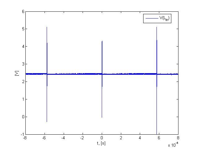
So I measured some signals to find out what went wrong. Apparently the boost charger is switching for a very short periods of time, most of the time it's idle. And I do not understand why as my battery voltage is well below OV threshold.
Here you see the boost switching node voltage:
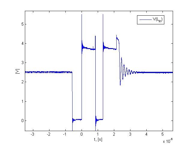
And a zoom on an activity period:
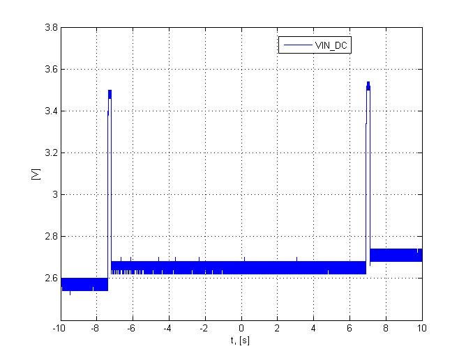
Here is a solar panel voltage, showing also MPPT sampling:
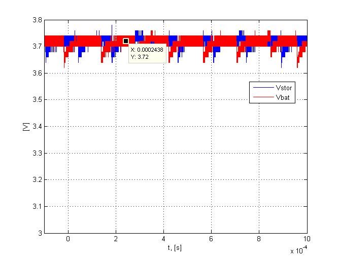
Vbat and Vstor voltages:
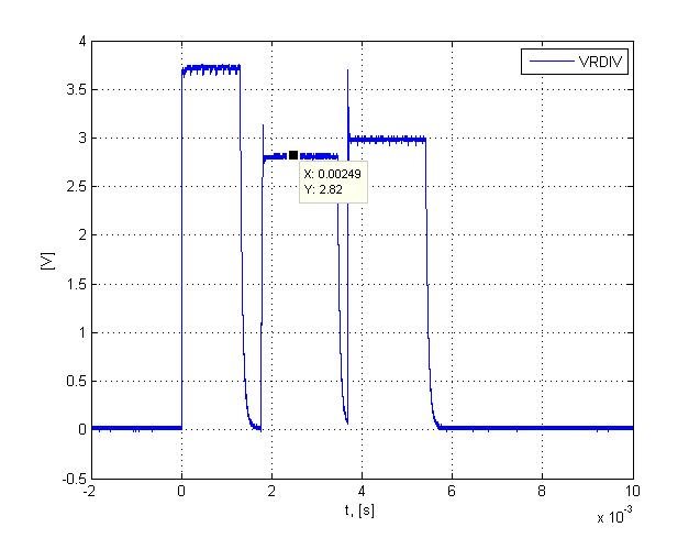
VRDIV voltage:
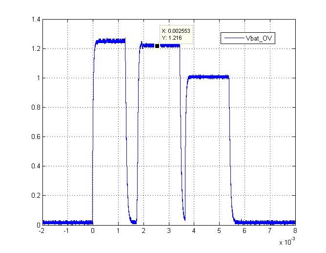
VBAT_OV voltage:
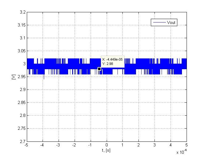
And, finally, Vout:
What bothers me is that a voltage level on VBAT_OV pin goes up to 1.216 V. Does this mean that over voltage is detected? I've double-checked (on the board) the divider, it's calculated to trip at 4.1V, and i have 3.72 on Vbat. Any ideas?
Anyway, if somebody could explain that super low duty-cycle of the boost converter, please share!)
Thanks in advance for any input!
Best wishes,
Olex


