This thread has been locked.

If you have a related question, please click the "Ask a related question" button in the top right corner. The newly created question will be automatically linked to this question.

Bq2060a E619 remaining capacity decrease quickly

Other Parts Discussed in Thread: BQ2060, BQ2060A

Hello:

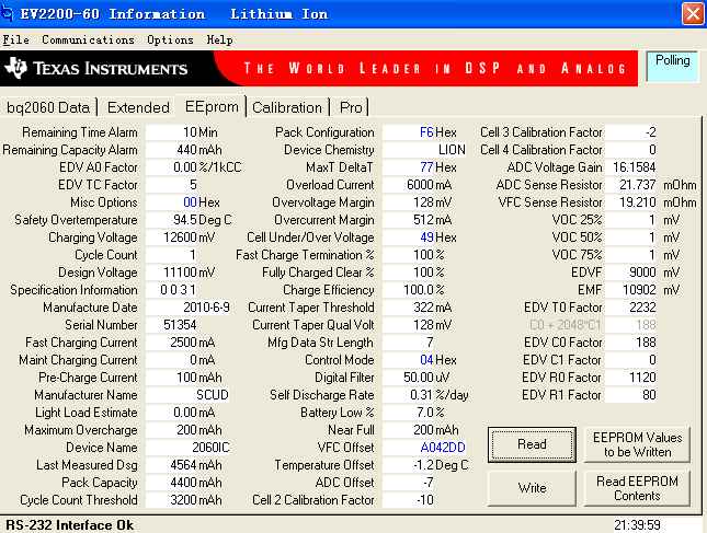
     My battery's remaining capacity decrease quickly(decreasing 1 mah or more several minutes) while there is no charge or discharge applying to the battery. The self-discharge is 031%

     1、 Is it the VFC incorrect? However i  re-sent the command 0x0653 to the manufacturer access. The remaining capacity still decrease abnormally compared to the normal value about 15mah per day(the pack capacity is 4400)

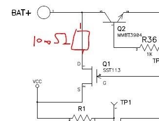
    2、 Is it related to the SST113?  The default bom device connected to Pin VCC is SST113.   In my company, for the device long delivery time, using other JEFT device  ( Vgs(off) is 0~-4V, Rds(on)= 50ohm) instead  of SST113..Should this lead to the RM decrease quickly?  Is there any special requires for the  JFET device ? 

            I have see the ceriteria for choosing the proper Vcc regulator JFET, but there is no detail for the bad effect if Vgs(off) is out of range.  

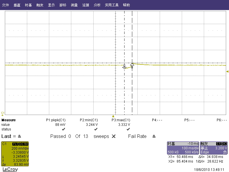
            I measure some voltages of Pin Vcc which battery's remaining capacity decrease abnormally.  The  Pin Vcc's voltage is about 3.3V..I think the Vcc value is within the range (2.7~3.7)..Should the Vgs(off)'s low too low or too high cause Vcc's high or low. If that, low Vcc's voltage cause RM's value increase itself while there is no charging current. high Vcc's voltage cause RM's value decrease itself while there is no dischargeing current??

           I want to know what result  if the JFET's Vgs(off) is below |-1.2|V and Vgs(off) is above |-3|V

Anyone who can help me, if need more details, please e-mail me: chenjingcong121@163.com

                                                                                                                                                                                     J.C Chen

                                                                                                                                                                                    Best regards


  • Chen xiansheng,

    Please use a JFET with pinch-off voltage less than -3V @ 10uA. It sounds like you are doing that, since it is regulating well at 3.3V. But, you should verify that the 3.3V VCC is stable during various modes of operation.

    Please review the first five pages of the attached app note regardng VFC calibration, PCB offset evaluation, Digital Filter and Light-load estimation. I suspect you may have some board offset current, which can usually be removed by using the alternate VFC calibration method.

    Rgds,

    Doug

    slva151.pdf
  • Dear Doug

             I am very glad for your reply.

             Now I use the JFET with Vgs(off) -0.5~-3V..I think it should meet with bq2060..But  we pre-production trial with 200pcs..199 pcs is under regular work for the update time intervals(640*13500/(256*n*Y%)) and capacity reduction(RM/256). One pcs is out of work, it reduced capacity about 300mAh within 12 hours.

              1、what further test should i do to this battery?...Re-calibrate the VFC to battery, or other? 

              2、In last post,you said VCC may be unstable during operation. However, In my fatory,after VFC calibration, we send the battery to learning for update FCC. and then some test. at last, Just storage. which steps may the VCC is problely unstable..


         Best regards..


  • Sounds like your JFET selection is good. I don't think any particular mode is important to check, just have a look at VCC to be sure there is no oscillation.

    For the bad battery I would start by measuring the voltage drop across the sense resistor with a sensitive voltmeter. Compare the measurement with a good unit. If there is a difference, then troubleshoot the board to find the source of the unwanted current. It might be a soldering or contamination issue.

    If measured current is the same in bad and good boards, then yes, please try to re-calibrate the VFC.

    If that doesn't work, then I suggest you swap IC's with a known good board. Does the problem follow the IC or the PCB?

  • Hi, Doug Williams

         I have followed your steps to check if there is current flow with the sense resistors first.  And there is no current.   Then I try to re-calibrate the VFC, Bq2060a update the RM in the normal mode.

         How could i to guarantee that  one  VFC calibration would be enough in mass-production ?

        Best regards

    J.C Chen

  • Dear Doug

                 Recently, RM decreaese quickly or increase to FCC are still be existed..


                                                                                                                     Picture 1

    1, Picture 1 is Vcc's wave. There is a wavefore. the Peak to peak value is 88mV..Coulde this affect the RM?

    2, I try swap the good IC with bad ones, After that , The RM indecrease normally.

    3. The attached file is JFET datasheet.MMBFJ113

    6663.MMBFJ113.pdf

    Another:

      1,Are that JFET's D S  inner-changeable?

      2. I connect a 100ohm resistor to the Q1.

         Does that have any effect to bq2060? 

    3. Read the SBS pack status"EINT", This bit is set while there is no current flow arross the sense resistors..The EEPROM screenshot is as below.


      I have try recalicated the voltage,current,VFC. But RM still may drops abnormally..