This thread has been locked.

If you have a related question, please click the "Ask a related question" button in the top right corner. The newly created question will be automatically linked to this question.

TPS63021 Design

Other Parts Discussed in Thread: TPS63021

Hi,

I am using TPS63021 Buck-boost converter for my application and I have successfully designed for the requirement. But I tried simulating the same circuit using WEBENCH and its schematics was nearly the same to what I designed. 

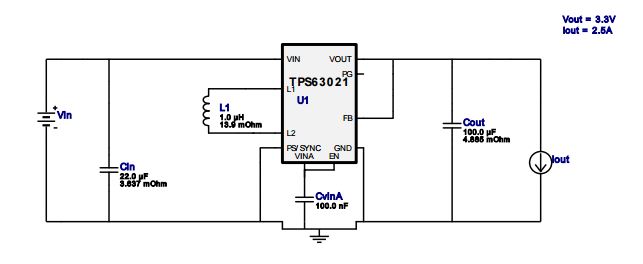
The schematics is shown below

I got the design report from WEBENCH which I have attached here.

For designing the Buck boost converter, I used the application note "SLVA535A -  Design Calculations for Buck-Boost Converters". I was able to find the important formulas for inductor selection, output capacitor selection etc.

But Where can I get the formula or design guide for rest of the parameters?

Can someone help me in knowing the entire design procedure covering all the parameters that are need in designing Buck-Boost, buck and boost?

(I have the design calculation app note for buck, boost and buckboost)

Thanks and Regards,

San

  • You found the right app note for designing your circuit with a buck boost converter.
    Usually if you follow the datasheet recommendations of each converter for choosing your inductor and capacitors you should not have any issue.
    The datasheet also recommends typical values for each component. I would start with the recommended components when designing my circuit.

    What do you mean by rest of the parameters?
    I see that you are using the TPS63021, did you check the recommended values for the passives on the datasheet ? Did you take a look on the EVM user's guide of this device?
  • Hi Santosh,

    A good way to start your design would be choosing the right operating frequency for optimal size and cost of components. Also, take into consideration the effect of Switching Frequency on efficiency of the converter and switching noise which may couple with the remaining system.The major components you need to select for these converters would be inductor, input and output capacitors which are dependent on the Switching Frequency. Most of the datasheets would help you in this design procedure.

    An other important thing to look for would be the control topology. There are many topologies available such as voltage mode, current mode, Hysteretic based- COT, DCAP and so on. Each has its own advantages and disadvantages of complexity in design (compensation), transient response etc.

    Here are a few useful links,

    https://training.ti.com/introduction-power-components

    https://training.ti.com/introduction-power-control-theory   

    Regards,

    Praveen

  • Hi Sabrina,

    Thanks for replying. From the design application note, I was able to get how to choose proper required inductor, input capacitor and output capacitor values. What I am trying to learn is, from that WEBENCH report, in the operating values section,

    1. CIN IRMS

    2. COUT IRMS

    3. Iin - Average Input current 

    4. IOUT_OP - Iout operating point.

    The rest of the parameters I was able to calculate. But I am not sure how to calculate these parameters. Is there any design guide that will help me understanding these?

    Thanks for you time.

    Regards,

  • Hi Praveen,

    Thanks for the link. I will make use of it.

    Regards,