This thread has been locked.

If you have a related question, please click the "Ask a related question" button in the top right corner. The newly created question will be automatically linked to this question.

TPS562209 - About bode plot

Guru 21045 points


Hi Team,


We measured the bode plot of TPS562209EVM at the following conditions.

And, my result of a measurement is as follows.


[Conditions]

-Vin=12V

-Vout=5V (Feedback resistor is 51ohm(injection resistor)+54.9kohm and 10kohm)

-Iout=2A

-L=4.7uH

-Cout=116uF (47uF + 47uF + 22uF)

-C9(Feed forward cap)= Open or 33pF


[Result]

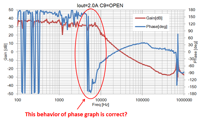
<No.1 bode plot (C9=Open) : Phase margin is 10.75deg>


<No.2 bode plot(C9=33pF) : Phase margin is 41.22deg>


However, the phase of “No.1 bode plot(C9=Open)” was different from my guess.

With my understanding, I think that it will be as written below(Figure 14. Measured).

http://www.ti.com/lit/an/slva546/slva546.pdf


Is “No.1 bode plot(C9=Open)” a proper result?

So, I would like to know whether this device is stability operation.

I'd appreciate it if you could give me some advice about that.


Regards,

Kanemaru

  • I've seen that happen occasionally. Plus 180 and minus 180 are the same. Sometimes the analyzer "flips" over.
  • Hi John-san,


    Thank you for your prompt reply!

    According to this bode plot, the phase margin is 10.75deg.

    Then, does this device do stable operation?


    Regards,

    Kanemaru

  • Hi John-san,

    Thank you always for your kind support!

    Would you tell me about the progress on this matter?

     I’m looking forward to hearing from you.


    Regards,

    Kanemaru


  • Hi Kanemaru,

    10 degree phase margin is too small, why you need to use 116uF output cap for this application? there has double pole of LC, the bandwith and phase margin will decrease with the increase of LC, because the LC double pole will apear more earlier with the increase of LC value.
    could you please use 47uF output cap and test it again?
    thanks!

    Eric
  • Hi Eric-san,


    Thank you for your response.

    Our customer can’t reduce the output capacitor of the around 116uF because the input capacitor of the load devices needs it.

    Therefore, they use the large feed forward capacitor at the following conditions to improve phase margin.


    [Conditions]

    -Vin=12V

    -Vout=5V (Feedback resistor is 51ohm(injection resistor)+54.9kohm and 10kohm)

    -Iout=1A

    -L=4.7uH

    -Cout=116uF (47uF + 47uF + 22uF)

    -C9(Feed forward cap)= more than 10pF


    I have a question.

    According to user’s guides of EVM, the maximum value of feedforward capacitor(Cff) is 10pF.

    If we use Cff more than 10uF, are there any some problem there?

    The would like to set the phase margin to 40deg at this conditions.


    If you contact to below my e-mail address or let me know your e-mail address,

    I can send the customer information.

    I’m looking forward to hearing from you.


    [my e-mail address]

    Kanemaru-h@clv.macnica.co.jp


    Regards,

    Kanemaru


    Regards,

    Kanemaru