This thread has been locked.

If you have a related question, please click the "Ask a related question" button in the top right corner. The newly created question will be automatically linked to this question.

TPS61222 Unregulated output at power-up, with load.

Other Parts Discussed in Thread: TPS61222, TPS61240

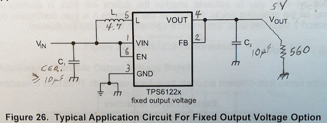
THE SETUP: I have wired a TPS61222 circuit, as shown in Figure 26 of the data sheet (SLVS776B, REVISED NOV. 2014). The inductor is 4.7uH, and the caps are both 10uF. For testing, I am using a 560 Ohm resistor to simulate the actual load. This draws about 8.9 mA from the output.

THE PROBLEM:  If I power up the circuit with the load in place, the output does not regulate to 5V. Varying the input from 2.5 - 5.0V provides an output of 3.5 - 4.5V.

I can then cause it to go in to regulation by removing and re-applying the load. Or, if I power it up WITHOUT a load, and then apply the load, it works fine.

Is this behavior normal for this chip? Any suggestions will be appreciated.

Thanks,

Ray

  • Please share the waveform of VIN, SW, VOUT when the problem is happen. and what about your layout and schematic.
  • Hi Jasper,

    Here are some pictures. Thanks for any advice. 

    We have an alternate chip picked out that will work, but I would like to figure out this problem for future designs.

    Ray

    Schematic (from the data sheet)

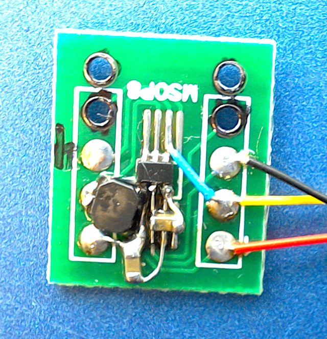
    Layout. (Far from ideal, just a slapped together test circuit.) Load resistor is out at the end of the 3" yellow and black wires. Input is between red and black.

    2.5V input & 5V output, when operating correctly.

    2.5V input & 4.7V output when NOT operating correctly.

    2.5V input & switch terminal (pin-5) when operating correctly. (Note that it is switching at about 100 KHz.)

    2.5V input & switch terminal when NOT operating correctly. (Note that it switches much slower, at about 10KHz.)

  • Hello all,
    Just hoping that someone might have an idea about the problem I'm seeing with the TPS61222 boost converter.
    The pictures in the post that I'm replying to show the schematic, layout (quick test circuit only), and waveforms.
    In the intended application, the circuit input will be 3.0-4.2V, with a 6-150mA load on the output.
    The chip operates great, except that it won't go into regulation if it has a load on it during startup.
    Any ideas?
  • Sorry for missing your reply.
    please try to place the COUT above the IC, and connect the COUT to VOUT and GND pin with the solder directly. the trace between the IC and COUT must be as short as possible.
    as the boost converter is sensitive to layout, i would suggest you do the really PCB.

    the TPS61222 can't support 150mA from 3V input because of current limit. please turn to TPS61240.
  • Thanks Jasper, That was exactly the problem. I thought I could get away with the test circuit on an adapter board, but the extra half inch that I had between the output and the output cap is what was killing it. Works fine now. 

    Also, thanks for the TPS61240 suggestion. I like that the output is open when the chip is disabled. That will eliminate the need for a load switch downstream from the boost reg.

    Ray