This thread has been locked.

If you have a related question, please click the "Ask a related question" button in the top right corner. The newly created question will be automatically linked to this question.

LM27313 current limit circuit question

Other Parts Discussed in Thread: LM27313, LM317, TL431, LM2735

Hola,

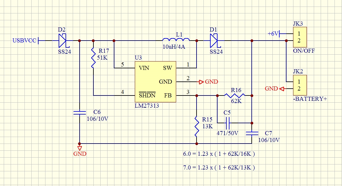
I'm using LM27313 as new project design as below circuit:

USBVCC is the power supply from NB, but the newest NB USB specification is 5V/1000mA and that will  causes the output power increased from 6V/400mA

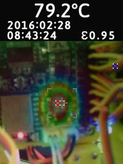
to 6V/1000mA so the LM27131's temperature will rising to 70'!

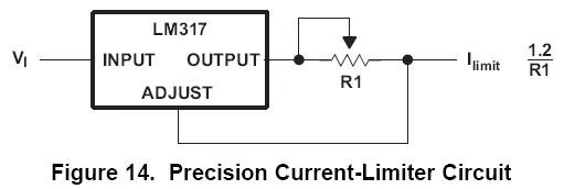
My question is that how can I limited the output current fixed at 500mA with this circuit?Can I use LM317 to limited the  output current?if yes, how can I integrated

them?


  • Hi Jacky,

    Thank you for the question. Let me move this to the appropriate forum.

    Thanks,
    Anston
  • Hola,
    Can someone help to provide me any suggestion for our application?
  • Can someone help to provide me any suggestion for our application?
  • Can someone help to reply this?Thanks ~

  • Hi Jacky,

    As far as I understand your system , you are charging 6V battery (probably PbAcid) using LM27313 with USB at its input . If that is the case , the better solution is to use single stage LM27313 Boost in Constant current ,Constant Voltage application(CC/CV) .

    The idea is to use something like this at the output and modify the feedback :

    This was done for 12 Volt battery . You can see there are two loops here one through R1 (the current sense resistance) as CC and other through Zener D3,R4,R3 as CV  .The offset in Feedback is added through Shunt regulator TL431 for reducing the looses across the current sense R1 . You might want to go through below reference design for more details 

    www.ti.com/.../PMP9456 

    Also you can refer to below application notes for more details on above described circuit :

    www.ti.com/.../slva595a.pdf                                                                                                                                                                                                              

    These examples are made on buck converter but  you can use the same concept to modify your feedback circuit in boost converter . 

    With Regards 

    Ambreesh 

  • Hola Ambreesh,

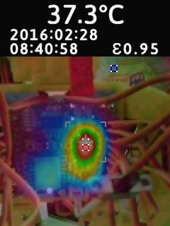
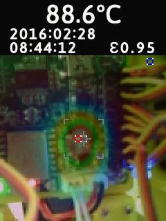
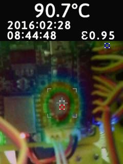
    Very clearly and helpful, thank you. Below figures are our thermal test result, can you give some advice for reduce temperature?

    Or you can advice another device with lower temperature which can meet our application. Thank you ~


    Brs

  • Hi Jacky ,

    If you want to use similar circuit for battery charging , you may look at LM2735 , whose internal FET has much lesser Rdson compare to LM27313(Lesser Conduction losses) . Work with Y version which is switching at 550KHz which will result in much lesser switching looses compare to LM27313 .Also you may choose from WSON or DGN package whcih has power Pad option for thermal dissipation . 

    Ambreesh 

  • Hola Ambreesh,
    Helpful and thank you very so much.