


Hi everyone,
We are trying to build a Quasi-Resonant Flyback converter with the UCC28600.
Input: 80V to 450V DC
Two outputs: 12V @ 0.83A (10W)
At first we tried providing 80V at the input and found out that Vdd rises linearly to about 13V, and the gate would turn on. Once the gate turns on, Vdd quickly drops to zero and the cycle repeats. The nominal load(14 Ohms) receives no voltage.
Later, we decided to debug the circuit by disconnecting the start-up circuit and the load, and provide a constant 13V at the Vdd. The results are below.

Vdd is now constant at 13V and the chip is always on. The yellow channel in the picture is the Gate of the MOSFET, which is 99% duty cycle, which yields no output in the secondary and thus no valley is present to trigger the valley detection logic. Since the Transformer is basically in DC state, a large currents goes through the drain because of the high input voltage. Beyond a certain value, the current becomes large due to the duty cycle and over-current protection triggerred.
Does anyone have any idea about this? Please let us know.
Much appreciated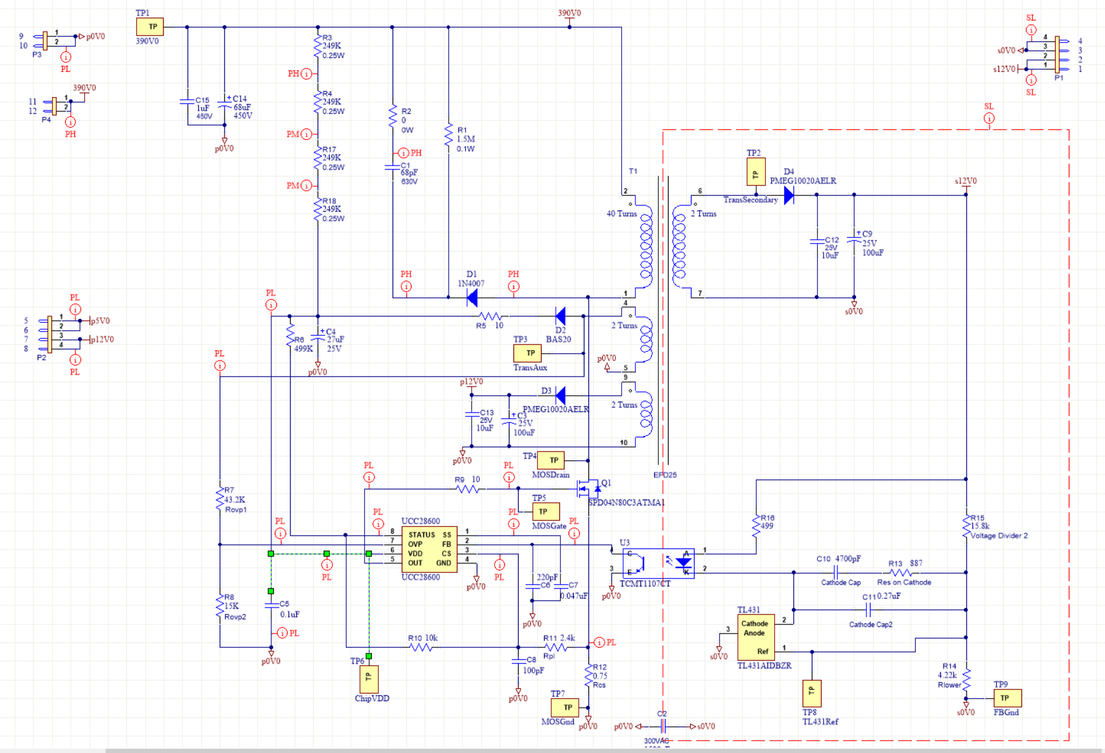 .
.

