This thread has been locked.

If you have a related question, please click the "Ask a related question" button in the top right corner. The newly created question will be automatically linked to this question.

UCC28600 secondary (elco) shortcircuit with safety (reinforce )isolation

Other Parts Discussed in Thread: UCC28600, UCC28730, UCC28704, UCC28740, UCC28710

Dear Sirs,

I am applying UCC28600 (Uin= 250V...900V; Uout1 = 24V_40W)

The shortcircuit on 24V_out - on the electrolytic capacitor-  the controller can go in hiccup state.

The current limit protection can not working, because the Cycle-by cycle power limit switch off the mosfet (Ton_ mosfet_min < 200..250nsec ) at 0.8V(CS pin) and can not  rich this pin the 1,25V, where the current limit protection appear.()

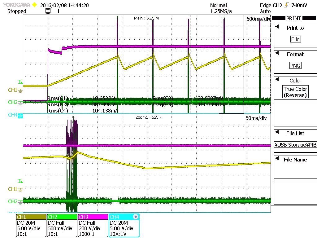
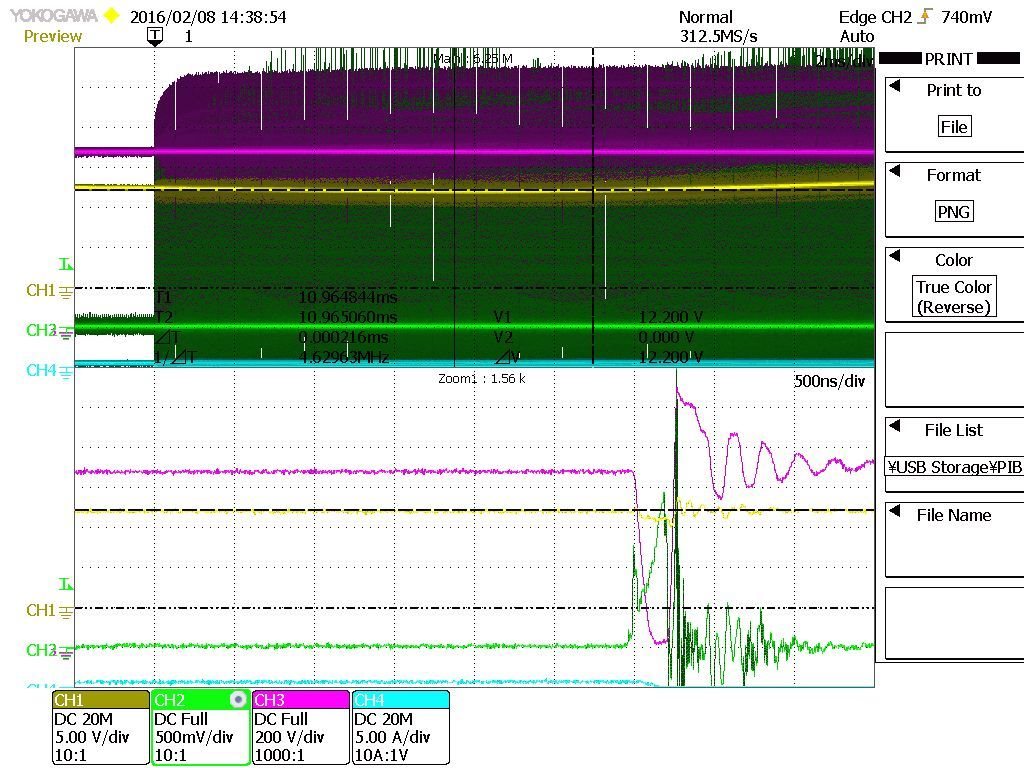
green: primary current;   purple: MOSFET U_CE

On the secondary side can flow 8x times of rated current rated - continuously and  can burn the wiring of transformer .How can I force the controller to increase the T_on_min time of Mosfet - so create a higher current - and Current limit protection can appear. Or how can I force the controller into hiccup state.

Thanks for your help: Jeno  Csizmazia

  • Jeno,

    I cannot see the waveform you posted, just a blank space. Can you re-attach the scope picture?

    Can you also post a schematic with values so we can help figure out what's happening?

    Thanks,
    Bernard
  • Dear Bernard,

    The attached file :

    the schematic- with multi outputs and transformer ratio;

    hicupp with diode src (yellow:aux _VDD; puple: UCE)

    and the thirds the capacitor src without  hiccup (green: primary current; purple: UCE; yellow: aux_VDD)

    Thanks for your help: Jeno

  • Jeno

    I am sorry but the hand-drawn sch tells me very little. I need to see more details, the components and values connected to each pin, the aux winding runs, the resistor divider on the OVP pin, Rcs value. etc.

    Is there a resistor between the Rcs shunt and the CS pin? Is there any filter cap on the CS pin? Etc, etc.


    From your plots, I cannot see any issue. For the first plot, the VDD pin rises to the UV on level, there is a burst of PWM switching, but after a short time (~20 ms) the burst stops due to one of the fault modes. Most likely due to CS fault > 1.25 V, but hard to tell for sure without more sch details. Then the controller goes to fault mode, and the VDD cap discharges. When Vdd reaches the UV off level (~8 V), the controller restarts in low power mode, allowing the VDD cap to recharge. When VDD reaches the UV on level (~13 V), the sequence repeats.

    From the second plot, the primary current is clearly >1.25 V - is this measured at the CS pin or at the Rcs shunt? Again, it's unclear if there is any series resistor of filter cap at the CS pin.

    In the datasheet page 17, it clearly states that the cycle-by-cycle 0.8 V CS limit will dominate, and the 1.25 v protection level is only for gross problems like transformer saturation. It specifically says that it is not intended to protect against output short-circuit.

    On page 31 fig. 22, it shows the output overload characteristic of the EVM, and the current does increase a lot as Vout drops - this is typical of a flyback controller with only peak current limit, because there is not correlation between peak current and avg output current as Vout drops.


    If output overload & short-circuit protection are very important in this application, I would recommend considering the UCC28740, or UCC28730, or UCC28710 (or a new device in the family UCC28704) - all of these use constant-current (CC) mode overload protection to ensure a constant limited fault current even as Vout decreases.

    Thanks,
    Bernard