This thread has been locked.

If you have a related question, please click the "Ask a related question" button in the top right corner. The newly created question will be automatically linked to this question.

PoE max & PoE fault issue

Other Parts Discussed in Thread: TPS23753

Hi

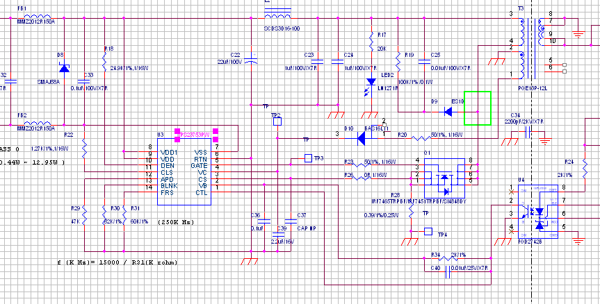
I am using a PoE circuit with TI's PD controller "TPS23753PW". When this circuit is connected to an active PoE switch, switch shows "PoE max" & "PoE fault" indications & there is no PoE output voltage.Power LED is blinking with OFF period is more than ON period.PD controller is configured in Class 0.Class resistor is 1.27K,Detection resistor is 24.9K & sense resistor of external MOSFET is 0.39E. PD controller's VDD pin has 48V input. This circuit's output is connected to 12V DC jack output through Diode ORing mechanism. 12V output DC jack section is working fine. I have replaced the PD controller with a new one, still there is no PoE output.Please suggest possible reasons for this issue.


AKV

  • It sounds like either 1) your appliance is drawing too much power, or 2) there may be an error in your design causing it to draw too much power. 

    FIrst carefully validate the built-up hardware against a known reference such as one of our EVMs, including all part ratings, installed direction, and transformer phasing. 

    Next, put 48V into the PoE front end, and troubleshoot the problem using the test cable described below.  Use caution and safe practices including having the (adjustable) test power supply current as low as possible while still regulating voltage.  If the converter appears to be working, measure the input power and make sure it meets the standard's requirements (<13W).

    You can build a test cable with an RJ45 on one end, and conductors tied together as (ref pin numbers)  1&2, 3&6, 4&5, and 7&8.  Power the PD via 1&2 - 3&6 or 4&5 - 7&8.

  • Hi Martin

    1.When I connected the faulty board to passive PoE injector it is drawing around 0.16A current where as a working board draws around 0.01A only

    2.The same design is working fine in 85 boards where as 7 boards only have this issue

    3.We made an observation in faulty board that, we are getting spikes at CS pin of PD controller with voltage above VCSmax(0.55V). As per data sheet,if the voltage at CS pin is above VCS max, the gate on time will be terminated regardless of voltage at CTL

    4. We have 12V adapter section ORed with PoE through diode ORing mechanism. I have isolated these two sections & still there is PoE issue


    Please let me know your suggestions


    AKV


  • It sounds like you have: 1)  Selected the wrong part or made a design error in you design (overstress), 2) installed different (wrong) parts or installed incorrectly, 3) received parts from an unreliable source.  Start by investigating for each and every part in the design.  Differences between good or bad may be either statistical (e.g. variance in breakdown voltage) or deterministic (e.g. wrong part).

    Since you state a 0.16A input current discrepency, but not the voltage, I will assume that it was at 48V.  The extra power is 7.68W.  Follow the power/heat.

  • hello,are you solve the problem? I met the same problem,


    48V input, first test TP2 is 7.34V(see datasheet Vc power need 9V),TP3 is 0.11V,but not output 12V.I change R20 (50E) to (33E),  test TP2 is 0.037V,TP3 is 0V,why, the IC burn out? i changed R20 to 50E,but TP2 alway  0.037V,TP3 0V. 12V always not output.

  • I cannot find any issue with your schematic but it is hard to read (a PDF would be better). If your feedback loop isn't working properly (or running open loop), you can exceed the rating of the Vc pin and damage the GATE driver output. Check GATE-RTN resistance with a meter.

    Check that your PCB match's a correct schematic. For problems of this sort, it is best to test the dc/dc converter first by applying a current limited low dc voltage between VDD/VDD1 and RTN (bypass the PD controller). Slowly ramp up the voltage above 9V and check circuit points with a scope to verify switching. Using this method can allow you to find the problem prior to blowing up the IC.

  • hi,Eric

    my  schematic is pdf file ,2133.SCHEMATIC1 _ PAGE1 PoE & DC & I.pdf

    I had change new U3,while input 48V,test TP2 is 7.36V,tp3 is 0.11V ,transformer T3 touch hot. restart again,test TP2 0.037V, U3's Vc(TP2) to earth 10E,same schematic and param,the U3(TPS23753PW) is so easy damage,or it  is so easy protect status. depressed....

  • TPS23753 is a very mature, reliable product. The problem is most likely a simple layout or BOM mistake. I will review your attached schematic more closely tomorrow to see if anything obvious shows up.

  • Try to add more bulk capacitance on the Vc pin (10-22uF) to help with start up. Also, what actual Q1 is installed? We have had some issues with certain FETs that are NOT logic level Vgs(th). Again, try to use a scope to debug your start up behavior and not a meter.

    "For problems of this sort, it is best to test the dc/dc converter first by applying a current limited low dc voltage between VDD/VDD1 and RTN (bypass the PD controller). Slowly ramp up the voltage above 9V and check circuit points with a scope to verify switching. Using this method can allow you to find the problem prior to blowing up the IC."

  • Hi,Eric,

       first thank you very much, I  had solved the program, the D5 diode is reverse, but i not understand no output 12V,that be able to damage the IC U3?

  • If the circuit runs open loop (since D5 was in backwards, the dc/dc will try to go to full duty cycle), the Vc supply will exceed the ratings of the IC and cause damage.