

Greetings from retired Mech engineer! I will be grateful for help:
Re PROPOSED CIRCUIT DIAGRAM 2016/03/17 (voltageRegulator02.jpg) below:
........................
This is a simple burglar alarm system. The Alarm control unit should maintain 13.8V at the battery, but is defective, and allows voltage up to more than 15V to be sustained on the connection to the battery.
Therefore I contemplate the scheme in the attached diagram.
As you can see, it has addition as shown in red, ie a voltage regulator using an LM2941CT is inserted between the unit and the battery, set at 13.8V.
QUESTION: Will 13.8V be maintained at the battery?
.........................
The purpose of the battery is, of course, to power the burglar alarm system when the 220 V domestic supply is interrupted. This definitely happens at times here in South Africa. At such times current must flow not from the control unit to the battery, but in the opposite direction. Therefore I have included in the scheme a further addition, namely the diode (in red) which bypasses the LM2941CT.
QUESTION:
Will this work satisfactorily? If yes, what type of diode will be suitable? Ideally, I imagine it should:
- have forward current capacity of 1A, with small voltage drop. (the demand is <500mA when the 220 V supply is down, and the unit is triggered and operating the siren.);
- pass a very low reverse current when the voltage at the battery is 13.8V, and the voltage on the input side of the LM2941CT is above 15V or a bit more, so as not to counteract the voltage regulation by the LM2941CT.
.........................
QUESTION:
Do I need to provide also something to protect the LM2941 from damage when the 220 V supply is interrupted but there is still 12 V or more from the battery on the output side of the LM 2941?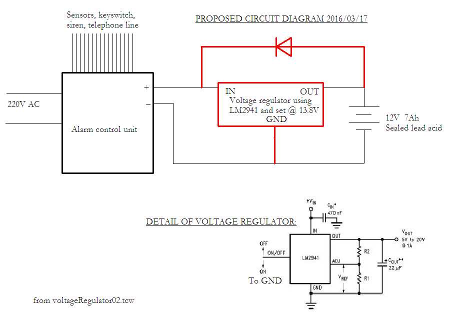

-
Ask a related question
What is a related question?A related question is a question created from another question. When the related question is created, it will be automatically linked to the original question.
